Stephanie Tupi, Winston Lynk, Megan Toney
Duke University
Durham, NC 27708
ABSTRACT
Our client is an independent, athletic woman who enjoys cycling in her spare time. Due to injuries sustained in a car accident, however, she now has limited left knee flexion and can no longer ride her bike. Our goal is to modify the client’s bike so that she can ride again. We have achieved this goal by devising a pivoting left crank arm. By allowing the pedal to drop to a lower height at the peak of the pedal motion, the pivot decreases the degree of knee flexion required for pedaling. The device was optimized for the client’s disability, but it can be adjusted to allow other individuals with different degrees of knee flexion to bike.
KEYWORDS
Bicycle; Knee flexion; Pivoting crank arm
BACKGROUND
Our client sustained various injuries in a car accident in 2003. One of these injuries prevents her from bending her left knee by more than 75° from full extension. She is not significantly limited in daily activities, but the injury has prevented her from pursuing one of her passions: bicycling. Because cycling requires 110° of flexion [1], she sought a solution to this flexion limitation that would allow her to ride her bike again.
The client and her occupational therapist tried resolving the problem by using a recumbent bike, which the user rides in a seated, reclined position. Unfortunately, she does not possess the range of motion necessary to operate a recumbent bike, and she prefers a standard riding posture. Shortened crank arms have also been implemented for riders with limited knee flexion [1], because they allow the knee to bend to a lesser degree at the peak of the pedal cycle. However, our client has a maximum flexion point near the axis of rotation of the crank arm, meaning only an infinitely small crank arm would allow her to clear the top of the pedal cycle. The pivoting crank arm solution, an idea patented in Canada [2], suited both our client’s preferences and needs. We expanded upon the patent to develop an optimized version for our client.
PROBLEM STATEMENT
This project’s overall goal was to modify the client’s bike in such a way that would allow her to ride again in a safe and comfortable manner.
DESIGN AND DEVELOPMENT
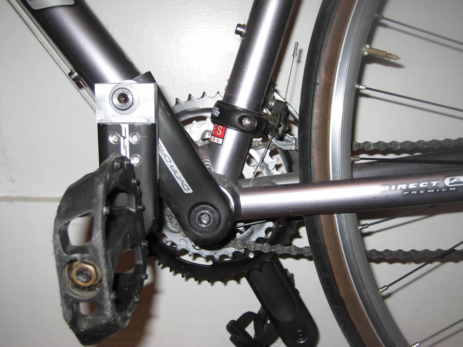
Photo 1: Final on bike.jpg (Click for larger view)
After initial discussions with our client and her occupational therapist, we felt that we had an adequate understanding of her needs and preferences pertinent to our task. She wanted a solution that allowed her to ride using both legs, featured a left side pedal motion as similar as possible to the right side, and kept her comfortably within her range of motion.
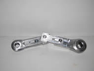 Photo 2: adjustable fasteners.jpg (Click for larger view)
 We researched six feasible solutions and compared them to our functional specifications, which took into account both user preferences and safety considerations. These proposed solutions included a sliding pedal motion, a shortened crank arm, an oval shaped gear, a recumbent bicycle with a stair climbing motion, a ratcheted crank arm, and a pivoting crank arm. After researching each idea, we eliminated most of these solutions. The sliding pedal motion violated the client’s preference of a similar right and left pedal motion. The shortened crank arm could not provide a short enough pedal cycle for the client’s needs, as explained above. Building an oval shaped gear system was not feasible on the given bike. The client had previously tested recumbent bikes and did not like the reclined position. The ratcheted crank arm did not offer any significant benefits over the pivoting crank arm, and it would not offer as smooth of a rotation. After discovering other instances in which the pivoting crank arm was beneficial for individuals with limitations similar to our client’s, and verifying that the solution met all functional specifications, we built a first prototype.

Photo 3: Sizing mechanism.jpg (Click for larger view)
Generally, the device works as follows. A pivot in the middle of the crank arm allows the outside section of the crank arm to overlap the inside section of the crank arm (Photo 1). There is no overlap at the bottom of the rotation; at this point the crank arm is the same length as a standard crank arm. At the top of the rotation, where the knee is bent maximally, the pivot positions the pedal several inches below the standard pedal position, thus decreasing the degree of flexion required to reach the top of the pedal cycle.
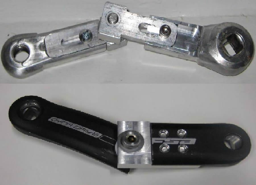
Photo 4: Design comparison.jpg (Click for larger view)
The first prototype comprised two halves of a bike crank arm connected by overlapping aluminum sections fastened together with a shoulder screw. The first prototype represented the functionality of the final device, but it presented two design challenges. First, the threading for the connecting shoulder screw partially entered the overlapping fastener, causing the assembly to tighten and eventually lock with repeated rotations. We addressed this issue by substituting a shoulder screw with shorter threading that did not insert into the overlapping fastener. Second, because the pivot was placed midway between the pedal and bottom bracket axles, the device was not customized for our client’s flexion capability to allow for maximum power output.
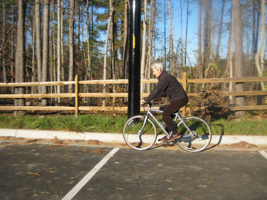
Photo 5: Client riding.jpg (Click for larger view)
We addressed the sizing issue of the crank arm with our second prototype, which was constructed so that the length of each crank arm section could be adjusted during client testing. We milled slots into the fasteners so that the lengths of the outside and inside crank sections could be varied relative to each other (Photo 2). A hand-held sizing mechanism was employed to ensure that the overall length of the device remained at the standard 170 mm crank length (Photo 3). By testing with the client, we determined the ratio of crank arm sections that would allow the client to generate maximum power while still remaining within her range of comfortable flexion (Photo 4).
The relative length information from prototype 2 was incorporated into the final product. The previous design was improved upon by considering safety and durability, including elements such as needle and thrust bearings to reduce rotational friction, and thread-lock or nylon-insert locknuts to prevent all screws from vibrating loose. Finally, we tested the modification with our client to ensure its functionality (Photo 5).
EVALUATION
We received the client’s approval on the pivoting crank arm idea before building prototypes. To verify that the concept would suit our client’s physical capabilities, we constructed a first prototype, which she tested on a stationary bike trainer. The second prototype was adjustable so that the client’s range of motion could be measured and used to optimize the final design. One challenge with the final design arose because the diameter of the shoulder screw was too small. This allowed a bending force to bend the screw during riding. Although a quantitative analysis was conducted to ensure that the minimum diameter was met to withstand shear forces, this calculation did not apply to bending moments. Thus, this problem was resolved by using a larger shoulder screw with a diameter of 5/8” rather than 5/16”.
DISCUSSION AND CONCLUSIONS
The obvious major advantage of the pivoting crank arm modification is that it allows individuals with limited left knee flexion to ride a bike. It also maintains maximal use of the left leg, and the left side pedal motion is similar to the right side to limit the necessity of additional coordination. Some power output from the left leg is lost with this solution because the shorter moment arm decreases the torque applied by the left leg. However, the addition of an eccentric chain ring [3] in the future could minimize this power loss by increasing the length of the crank arm to greater than a standard length during the pedal down stroke, where force is at a maximum. This modification can be implemented for any cyclist with limited knee flexion; the adjustable-length crank arm we developed would simply need to be customized for the user’s flexion ability.
REFERENCES
- Mackie, Brian and Bill McGuiness. “Prosthetists get cranked: Bicycling and the
transtibial amputee.” Amputee Web Site. 2004. 13 September 2008.
http://www.amputee-online.com/amputee/mackie.html
- Buston, William, Knight, Scott, and Daniel Mead. The Hinged crank arm.
Canadian patent application 2437716 August 18 2003.
- Hue, Olivier et al. “Enhancing cycling performance using an eccentric chainring.”
Official Journal of the American College of Sports Medicine. 2001.
ACKNOWLEDGMENTS
This project is supported by the National Science Foundation under Grant No. BES-0610534. Various individuals were valuable resources throughout the design process. Dr. Laurence Bohs educated our team on the engineering design process and gave feedback on our design throughout the process. Dr. Mark Palmeri provided spare parts for prototypes as well as design suggestions. The employees of The Bicycle Chain in Durham, NC, supplied bike parts and expertise. Sue Cheng, our client’s occupational therapist, helped us in clarifying our client’s needs and abilities. Steve Earp taught us to use the necessary machines and suggested methods of improving the durability and safety of our device.
Stephanie Tupi, 1470 Redfern Drive, Pittsburgh, PA 15241
Winston Lynk, 826 Monterey St., Coral Gables, FL 33134
Megan Toney, 65 Laurie Lane, Wrentham, MA 02093