The Effects of Pelvic Belt Anchoring Location on Wheelchair Seating System Loads in Frontal Impact Motor Vehicle Crashes
Miriam A. Manary1,Nichole L. Ritchie1 , Carol A. C. Flannagan1 ,
Gina E. Bertocci2 , Lawrence W. Schneider1
1 University of Michigan Transportation Research Institute
2 University of Louisville
ABSTRACT
Determining worst-case wheelchair seating system loading conditions in frontal impact crash tests is necessary to help develop a RESNA standard that evaluates seating systems used as seats for motor vehicle travel. Eleven sled impact tests were conducted to determine the effect of pelvic belt anchoring location (to the wheelchair or vehicle floor) and seating support surface type (fabric or planar) on seating system loading. Observed seat loads showed that the normal and shear forces were significantly higher with the wheelchair-anchored belt and/or the fabric seating conditions. Back support load data showed that neither pelvic belt anchoring nor seating type were significant factors. The results suggest that seating systems should be tested with wheelchair-anchored pelvic belts to create worst-case seat loading.
KEYWORDS
Seating system crash loads, wheelchair transportation safety, standards development, dynamic testing, crashworthiness
BACKGROUND
Section 19 of ANSI/RESNA Wheelchair Standards Volume 1, Wheelchairs Used as Seats in Motor Vehicles (often called WC19), and the draft standard, Section 20 of RESNA Wheelchair Standards Volume 4, Seating Devices for Use in Motor Vehicles (WC20) aim to improve protection of wheelchair-seated occupants in motor-vehicle crashes by establishing design and performance criteria for wheelchairs and wheelchair seating systems (1,2). WC19 addresses complete wheelchairs consisting of a seating system and a frame/base. WC20 extends this standard by allowing independent testing of a seating system using a surrogate wheelchair base (SWCB). Independent testing of seating systems is important because an individual’s seating and positioning needs may require a particular seat-base pairing and it is not possible or practical to crash test every seat-base combination.
Currently, WC19 specifies testing with a wheelchair-anchored pelvic belt while the draft version of WC20 uses a vehicle-anchored pelvic belt for the dynamic test. The rationale for testing wheelchairs with a wheelchair-anchored pelvic belt is to provide incentive for wheelchair manufacturers to offer this important feature that promotes better belt fit, provides the person in the wheelchair with a level of safety that is not dependent on assistance from the transportation provider or a caregiver, minimizes intrusion into the personal space of the wheelchair users by third parties, and reduces the problem of broken/dirty lap belts that many find unacceptable for use. Both poor belt fit and nonuse of lap and shoulder belts have been shown to be key factors contributing to an increased injury risk for wheelchair-seated travelers in the field (3).
Despite these advantages of wheelchair-anchored belts, the proposed WC20 test protocol uses a vehicle-anchored pelvic belt to crash test seating systems because the limited data available to date suggest this condition generates higher loads on the seating system. An additional consideration is that a vehicle-anchored occupant restraint is the most common restraint scenario in the field. The difference in pelvic belt anchoring configurations between these standards has raised concerns about: whether seating systems and wheelchairs should be tested using both pelvic belt anchorage configurations, issues of product labeling and liability, and what conditions truly produce the worst-case seating system loads.
OBJECTIVE
The primary objective of this study was to determine whether a wheelchair-anchored pelvic belt or a vehicle-anchored pelvic belt generate worst-case loading conditions for seating systems subjected to moderate-to-severe frontal crash conditions when a wheelchair is used as a motor vehicle seat. To make the findings applicable to a wider range of seating system styles two types of seating, fabric (sling) and planar (solid) seating systems were tested.
METHODS
A series of eleven 48 kph/20-g frontal impact sled tests were conducted to determine the effect of pelvic belt anchoring location on normal and shear loads directed to the wheelchair seat and back support. Two typical but distinct seating types were used for testing: a vinyl fabric (i.e., sling) seat and back support and a solid, planar metal seat topped with a 38-mm vinyl-covered commercial seat cushion paired with a 19-mm marine-grade plywood back support cushioned with 25 mm thick nylon-covered foam pad. The planar seating system was assembled to replicate the materials and construction of a commercially available solid seating system. Photos of the two seating systems are provided in Figures 1a and 1b. A full factorial 2x2 experimental design was used and each combination of belt-anchoring condition and seating system was tested three times, with the exception of the wheelchair anchored pelvic belt and fabric seating condition that was tested twice.
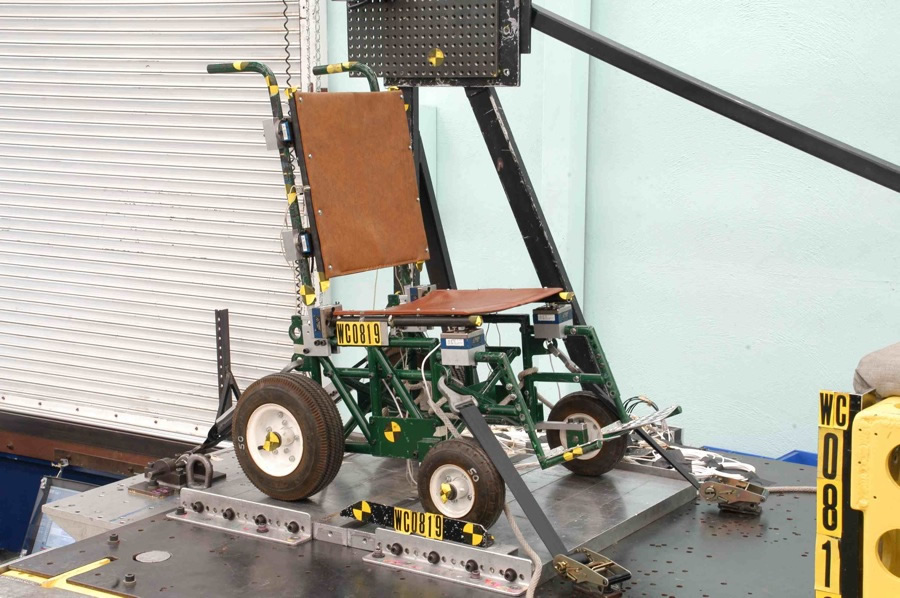
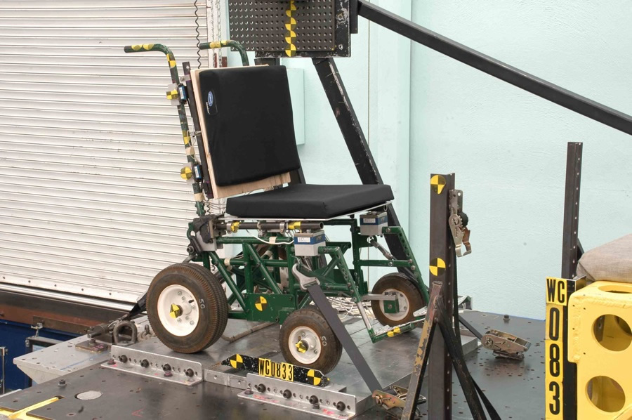
Figure 1. (Click for larger view)
All tests were conducted using the surrogate wheelchair base (SWCB) described in Annex D of the draft standard WC20 that was specially-equipped with triaxial load cells to quantify the load delivered to the seat rails at four locations (right front, left front, right rear, and left rear) and the load delivered to the back support canes at four locations (upper left, upper right, lower left and lower right). The data from these load cells were adjusted to compensate for the inertial effects of load-cell mass on the force measurements. The SWCB design includes deformable elements that represent typical commercial wheelchair base compliance at the front casters and the base of the back support canes and these elements were replaced after each test.
Tests were conducted in accordance with the frontal crash test protocol of Annex A of the draft standard WC20 using a four-point strap type tiedown system to secure the forward facing wheelchair to the sled platform. A 75-kg, midsize male Hybrid III anthropomorphic test device (ATD or “crash test dummy”) represented the nominal wheelchair user and was restrained by a properly-positioned, surrogate three-point belt. The lower ends of the pelvic belt of the occupant restraint were anchored either to the SWCB near the seat-to-seatback frame junction or to the simulated vehicle floor behind the wheelchair. For all tests, the upper shoulder belt anchor point was located at the WC20-prescribed location on the simulated vehicle sidewall behind and above the occupant shoulder. Pre- and post-test photos along with high-speed digital video were used to document each test. Data on the seat and back support loads, ATD accelerations, and belt tensions were collected, filtered and processed per the SAE J211 standard (4). Figure 1 illustrates the two seat types.
RESULTS
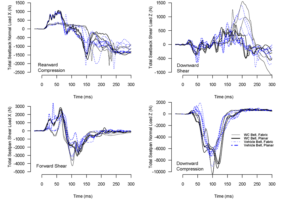
Figure 2. (Click for larger view)
In each test, the SWCB was effectively secured to the sled during impact and the seating system remained intact and firmly attached to the SWCB. Figure 2 shows the load versus time curves for the total normal and shear forces recorded at the seat rails and back support canes in the eleven conditions, where the back support normal and shear loads are shown on the top plots and the seat compressive and shear loads are shown on the bottom two plots. As these data show, the impact event can be divided into two phases: the initial loading during which the ATD moves forward and stops against the three-point belt system (roughly the first 150 ms of the data) and the rebound phase where the ATD moves rearward into the seat system later in the test (after 150 ms). The traces in Figure 2 show that the peak normal force on the seat is downward, compression loading during the initial portion of the impact event and that the peak seat shear force is directed forward along the seat surface toward the front of the wheelchair and occurs at approximately the same time as the peak compressive force (during the interval between 100-125 ms). For the back support, the peak normal load is a compressive force directed rearward into the back support surface and occurs in the second phase of the impact event (between 150 and 250 ms). The peak shear load data is usually directed upward, during ATD rebound. The individual test load traces from the back support are not as tightly grouped and less repeatable, particularly during rebound and are indicative of the more chaotic nature of the ATD interaction with the seatback.
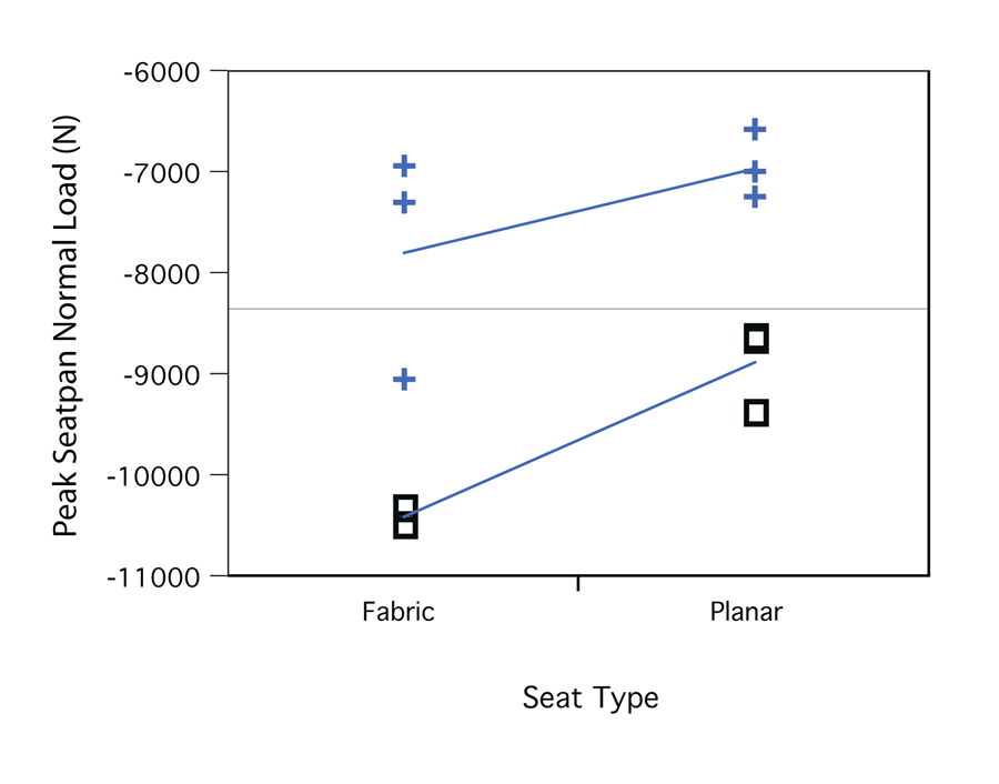
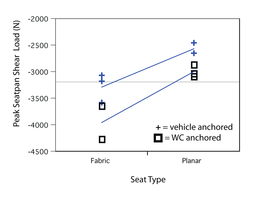
Figure 3. (Click for larger view)
The peak values for seat normal, seat shear, back support normal, and back support shear loads for each test were analyzed using ANOVA techniques to quantify the effects of pelvic belt anchor point location and seat type. For seat normal loading, significant independent effects were found for both pelvic belt anchoring configuration (P=0.0005) and seating type P=(0.0231) with no significant interaction term between the two factors. The model estimates that a wheelchair-anchored pelvic belt increases the downward, normally-directed force into the seat by an average of 2230 N more than the vehicle-anchored pelvic belt condition and that fabric seating increases compression load by an average of 1126 N over the planar seat condition. Similarly for seat shear loading, significant and independent effects were found for the factors of belt anchoring (P=0.0103) and seating type (P=0.0011) with no significant interaction term. In this loading mode, a wheelchair-anchored pelvic belt increased peak shear force in the forward direction by an average of 552 N more than the vehicle-anchored pelvic belt condition and a fabric seat was shown to increase forward shear loading by an average of 840 N more than the planar seating condition. Figure 3 further illustrates the magnitude and strength of these effects. Analysis of the back support normal and shear loads showed no systematic effects of belt anchoring or seating type on peak loads but more variability in normal and shear load magnitude was observed with fabric seating.
CONCLUSIONS
Eleven frontal-impact tests were conducted to determine if worst-case seat and back support loading is associated with anchoring the pelvic portion of the occupant restraint system to the wheelchair or the vehicle floor. To make the test series relevant to a wider range of wheelchair seating system designs, both fabric (sling) and solid, planar seating support surfaces were tested. The results show that the highest normal and shear loads for the seat are generated by using a wheelchair-anchored pelvic belt and suggest that both WC19 and WC20 should test wheelchair and seating systems with a wheelchair-anchored pelvic belt. These data can also provide estimates of peak seating system and base/frame loads that can help manufacturers design crashworthy products.
REFERENCES
- American National Standards Institute/Rehabilitation Engineering and Assistive Technology Society of North America (ANSI/RESNA). (2000). Section 19 ANSI/RESNA WC/Volume 1: Wheelchairs Used as Seats in Motor Vehicles. Arlington, VA.
- RESNA Committee on Wheelchairs and Transportation (2008). Draft version of RESNA WC/Vol.4, Section 20: Seating Systems Used in Motor Vehicles.
- Klinich, K,. Moore, J., Manary, M., Schneider, L. (2006). Use and performance of ocupant restraint systems for wheelchair users in real-world crashes. Proceedings of the RESNA 29th International Conference on Technology and Disability. Arlington, VA.
- Society of Automotive Engineers, (2008) Recommended Practice J211: Instrumentation for Impact Test, SAE Handbook, Warrendale, PA.
ACKNOWLEDGEMENTS
This study was funded by the National Institute on Disability and Rehabilitation Research (NIDRR) Rehabilitation Engineering Research Center (RERC) on Wheelchair Transportation Safety, Grant # H133E060064. The opinions expressed are those of the authors and do not necessarily reflect those of the NIDRR.
Miriam A. Manary, Biosciences Division, University of Michigan Transportation Research Institute
2901 Baxter Road, Ann Arbor, MI 48109 (734) 936-1108