1 Marquette University, Milwaukee, WI; 2 Orthopaedic and Rehabilitation Engineering Center, Milwaukee, WI; 3Medical College of Wisconsin, Milwaukee, WI; and 4 Shriners Hospital for Children, Chicago, IL
ABSTRACT
Previous studies have evaluated upper extremity (UE) kinetics during Lofstrand crutch-assisted gait but failed to include the involvement of cuff forces and moments. The goal of this study was to develop a novel instrumented Lofstrand crutch system with two six-axis dynamometers, which completely define the UE kinematics and kinetics. The instrumented crutches were used with a validated kinematic model of the UEs that is ISB compliant. The system and its applications are demonstrated in children with osteogenesis imperfecta (OI), spinal cord injury (SCI) and cerebral palsy (CP). Evaluating the UE dynamics of crutch users may ultimately help to reduce longer-term pathologies due to excessive loading or inappropriate gait patterns.
KEYWORDS
Lofstrand crutches, upper extremity dynamics, kinematics, kinetics, motion analysis, gait
BACKGROUND
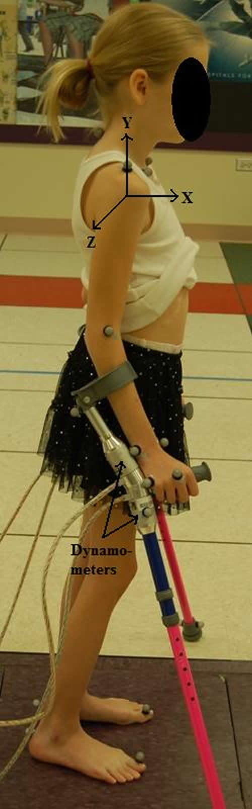 Photo 1: Lofstrand crutch system and joint coordinate system
 Recognition of UE arthropathy and degenerative arthritis associated with longer-term assistive device use has been reported in current literature [1, 2]. Individuals with weaker lower extremities frequently rely on assistive devices such as walkers, canes and Lofstrand crutches for ambulation. Among these, walkers provide the most support but restrict activities of daily living (ADLs). Canes provide the least support and most freedom to perform ADLs. Lofstrand crutches strike a balance between support and freedom required to perform ADLs.
A few previous studies have quantified UE dynamics during Lofstrand crutch-assisted gait. Among those, Slavens et al. investigated a pediatric population and established a standardized UE inverse dynamics model [3]. However, the cuff forces and moments where considered negligible [3]. Also, the placement of the sensor at the tip of the crutch increased the moment of inertia during crutch swing. Requejo et al. presented a system with a lower moment of inertia by locating the sensor proximal to the handle of the crutch [4]. However, this system evaluated only the cuff moments from which the cuff forces were derived [4]. This crutch model was applied to a single adult SCI subject. Liggins et al. used a crutch system similar to Slavens et al. but did not fully quantify the UE dynamics [5].
The goal of this study was to develop a pediatric Lofstrand crutch model, which provides a complete quantitative description of the UE dynamics during crutch-assisted gait. This model is standardized based on ISB recommendations [6] and includes both cuff forces and moments. The system is versatile for application with various pathologies. The system can evaluate repetitive loading during ambulation and may prove helpful to develop gait strategies for safer, longer-term crutch usage.
RESEARCH QUESTION
The objective of this study is to develop a system capable of characterizing UE joint dynamics in children using Lofstrand crutches. The goal is to identify UE joint loading patterns associated with various pathologies. Studies have shown that Lofstrand crutches require loading of the UEs up to 50% of body weight, without including the involvement of the cuff forces and moments [7]. Evaluation of the UE kinetics in a pediatric population of OI, SCI and CP is used in this study to gain further insight into the demands placed on the UEs. We hypothesize that these populations will exhibit similar joint load demands.
METHODS
Kinematic Model
The UEs were modeled using seven rigid body segments, which were the thorax, upper arms, forearms, and hands. Each crutch was modeled using three rigid body segments defined by the cuff, handle and tip of the crutch. Thirty-two reflective markers were used to define these segments.
Joint centers were calculated using the markers and subject specific anthropometric data. Joint coordinate system axes were based on ISB standard recommendations [6]. The thorax model was based on the study done by Nyugen et al. for analyzing thorax kinematics in children with myelomeningocele (MM) [8]. A Z-X-Y Euler rotation sequence was used to define rotations of the segments.
Kinetic Model
The kinetic model was developed using the inverse dynamics Newton-Euler approach [9]. The reaction forces and moments from the instrumented crutches are required for solution of the model. The Newton-Euler equations were used for each joint to compute the forces and moments.
Instrumentation
Crutches were instrumented with six-axis FS-6 dynamometers (AMTI, Watertown, MA) to measure the applied reaction forces and moments. Each crutch consists of two dynamometers placed above and below the handle (Photo 1). Thin co-axial cables are used to multiplex crutch data for acquisition. The analog data from the dynamometers are amplified using AMTI MSA-6 high gain amplifiers. The weight of the dynamometers was 0.10 kg each and the weight of the crutch was 0.43 kg. All force and moment data were validated and calibrated with static and dynamic validation protocols.
Patient Population
One subject from each of the three different populations with prior experience using Lofstrand crutches was selected. A subject with type I OI, 16-year-old female participated. Her height and weight were 1.4 m and 43.8 kg respectively. The subject with SCI was a 7-year-old female of height 1.2 m and weight 20.4 kg. The subject with CP was an 11-year-old female and her height and weight were 1.4 m and 24.9 kg respectively
Data Collection, Processing and Analysis
The subjects were asked to walk with the bilateral instrumented Lofstrand crutches on a 6-meter walkway for 3 trials at a self-selected pace and gait pattern. A Vicon motion analysis system, with 14 infrared cameras, was used to capture 3D motion of the reflective markers placed on the bony landmarks of the subject and the crutches. Data were averaged over 3 trials. Foot heel strike to heel strike was defined as 100 % gait cycle with data being processed every 1 % of the gait cycle.
Cadence, walking speed, stride length and stance duration were calculated for each subject. Forces and moments were determined. Mean forces and moments were normalized to % body weight (BW) and % body weight multiplied by height (% BW*H).
RESULTS
All UE joint data was collected and analyzed. The shoulder consistently showed the highest joint reaction forces and moments and is reported here. Temporal distance parameters of the three subjects are reported (Table 1.). It was seen that all subjects adapted a similar two-point gait pattern. The OI subject demonstrated maximum cadence, walking speed and a high stride length. This subject had the lowest range of motion, peak forces and moments at the shoulder. The SCI subject had the lowest walking speed and stride length, with the highest stance duration. The range of motion and the forces at the shoulder were highest in this subject. The subject with CP demonstrated lowest cadence and stance duration while the highest stride length. Highest peak moments at the shoulder were observed in this subject.
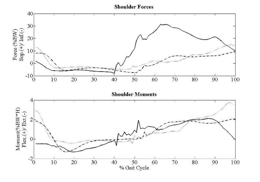 Figure 1: Shoulder forces and moments
The sagittal plane joint reaction forces and moments occurring at the shoulder are demonstrated in Fig 1. Highest force was seen in the subject with SCI. Superiorly directed compression shoulder forces were sustained for up to 50% of the gait cycle while peaking at 31.33 % BW. The shoulder forces for the subjects with OI and CP have similar patterns where superior compression forces were sustained for up to 45% of the gait cycle. Moments are similarly varied among the three pathologies. The maximum shoulder flexion moment was seen in the subject with CP.
DISCUSSION
| Subject | Cadence (Steps / min) | Walking speed (m/s) | Stride Length (m) | Stance Duration (%) | Range of Motion (degrees) | Peak Forces (%BW) | Peak Moments (%BW*H) |
|---|---|---|---|---|---|---|---|
| OI | 103.39 | 0.78 | 0.90 | 65.57 | 25.15 | 9.14 | 2.05 |
| SCI | 93.99 | 0.49 | 0.62 | 70.76 | 34.23 | 14.96 | 3.78 |
| CP | 78.59 | 0.62 | 0.95 | 56.14 | 42.63 | 31.33 | 2.11 |
Our data indicates that the subject with OI was the least dependent crutch user since she had the least superiorly acting compression forces and flexion moments at the shoulder. This is consistent with an effort to reduce overall skeletal loads to minimize fractures. On the other hand, the subject with SCI was the most dependent crutch user, which is consistent with the slower walking speed and higher forces occurring at the shoulder. The subject with CP moderately loaded her UEs during crutch ambulation, but demonstrated high flexion moments during the gait cycle. Even though all the subjects showed similar two-point gait patterns, the force and moment loading varied. It may be significant that several joint load patterns exhibited forces exceeding those of typical wheelchair users [10].
Results of this study support the use of this technically validated crutch system to evaluate UE ambulation patterns during Lofstrand crutch-assisted gait. Limitations of the previous studies have included limited number of sensors, sensor location, sensor characteristics and a non-standardized model. These limitations were addressed by designing a novel crutch system that included more sensors placed strategically for complete analysis of the UE dynamics.
Earlier work by our group indicates that crutch-assisted gait patterns directly affect UE joint load distribution [3]. The current kinetic model will allow study of joint load optimization through activity modification, gait training and crutch re-design. Further study with this system may also offer valuable insight for crutch prescription, placement patterns (reciprocal, swing-through, swing-to) and longer-term usage effects.
REFERENCES
- Opila, K. A., Nicol, A. C. and Paul, J. P. (1987). Upper limb loadings of gait with crutches. Journal of Biomechanical Engineering, 109, 285-290.
- Klimaitis, A., Carroll, G. and Owen, E. (1988). Rapidly progressive destructive arthropathy of the shoulder--a viewpoint on pathogenesis. Journal of Rheumatology, 15, 1859-1862.
- Slavens B. A., et al. (2009). Upper extremity dynamics during Lofstrand crutch-assisted gait in children with myelomeningocele. Gait and Posture, 30, 511-517.
- Requejo P. S., et al. (2005). Upper extremity kinetics during Lofstrand crutch-assisted gait. Medical Engineering and Physics, 27, 19-27.
- Liggins A.B., et al. (2002). The case of using instrumented crutches during gait analysis. Proceedings of the IEEE 28th Annual Northeast Bioengineering Conference, 15-16.
- Wu G., et al. (2005). ISB recommendation on definitions of joint coordinate systems of various joints for the reporting of human joint motion. Part II: Shoulder, Elbow, Wrist and Hand. Journal of Biomechanics, 38(5), 981–992.
- Melis E. H., Torres-Moreno R., Barbeau H., Lemaire E. D. (1999). Analysis of assisted-gait characteristics in persons with incomplete spinal cord injury. Spinal Cord, 37, 430–439.
- Nguyen T.C., Baker R. (2004). Two methods of calculating thorax kinematics in children with myelomeningocele. Clinical Biomechanics, 19(10), 1060–1065.
- Zatsiorsky V.M. (2002). Kinetics of Human Motion. Champaign, IL: Human Kinetics.
- Collinger J.L., et al. (2008). Shoulder biomechanics during the push phase of wheelchair propulsion: a multisite study of persons with paraplegia. Archives of Physical Medicine and Rehabilitation, 89, 667-76.
ACKNOWLEDGMENTS
This work is supported by the Orthopedic and Rehabilitation Engineering Center, (OREC), Shriners Hospitals for Children and Dr. Ralph and Marian Falk Medical Trust.
Author Contact Information:
Neha Bhagchandani, BS, Marquette University, 735 N. 17th Street, Suite 105, P.O.Box 1881, Milwaukee, WI 53201-1881, Office Phone (414) 378-9753 EMAIL: neha.bhagchandani@marquette.edu
Word Version PDF Version