MIT Mobility Lab, Massachusetts Institute of Technology, Cambridge, MA, USA
ABSTRACT
This document presents the design process, analysis, and fabrication used to create a prototype Leveraged Freedom Chair (LFC) for trial in East Africa. The LFC is a lever-powered, wheelchair-based mobility aid designed specifically for use in the developing world. Its drivetrain optimally converts upper body in a wide range of terrains, giving the LFC operational capabilities that extend beyond those of currently available mobility products. All of the moving parts in the LFC are made from bicycle components, which allow it to be manufactured and repaired anywhere in the developing world. In August 2009, eight LFC prototypes were produced in Kenya for $195.28 each, affirming that the chair can be built using local tools and materials for the same price as existing mobility aids.
KEYWORDS:
Lever, wheelchair, variable speed, developing countries, international development
INTRODUCTION
The Leveraged Freedom Chair (LFC) is a lever-powered, wheelchair-based mobility aid designed specifically for use in the developing world. The drivetrain enables an LFC user to negotiate varied terrain ranging from steep hills to sandy roads to muddy walking paths. For indoor use, the LFC can operate as a regular push rim wheelchair by simply removing the levers. The motivation behind this project is to create a single mobility aid that fully meets the usage requirements of people with disabilities in developing countries and transcends the capabilities of currently available technology. Western-styled wheelchairs are inefficient to propel [1] and are exhausting to use for long distances on rough roads. Hand-powered tricycles, which are preferred if the user has adequate torso stability [2], are more efficient to propel than a wheelchair [1, 3, 4], but are difficult to maneuver through sand and up steep hills and are much too large to use within the home. There is great demand for a device like the LFC, as 70% of the 20 million people in the developing world who require a wheelchair but do not have one live in rural areas [5-7].
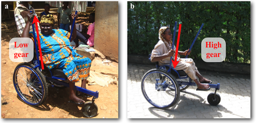 Figure 1. Moving hand position on the LFC levers changes mechanical
advantage. a) Placing hands high on the levers generates high torque
and an effective low gear. b) Placing hands low on the levers creates
high angular velocity in the drivetrain and an effective high gear.
Figure 1. Moving hand position on the LFC levers changes mechanical
advantage. a) Placing hands high on the levers generates high torque
and an effective low gear. b) Placing hands low on the levers creates
high angular velocity in the drivetrain and an effective high gear. Instead of using multiple gears to change speed, an LFC user varies mechanical advantage by sliding his or her hands up and down the levelers, as shown in Fig. 1. Changing user geometry instead of machine geometry enables the LFC drivetrain to be composed of a lightweight, low-cost, single gear ratio chain drive made from bicycle components found anywhere in the developing world. Human power and force output capabilities [3, 8] were used to determine a lever size and drivetrain geometry that enables the user to efficiently travel on smooth surfaces and gentle grades, and produce enough torque to overcome harsh terrain. The lever system achieves a 4:1 change in mechanical advantage, equating to leverage that ranges from 0.42X to 1.65X a standard wheelchair hand rim. In comparative user trials, the LFC demonstrated capabilities that exceed those of any mobility aid currently available in the developing world; it was able to cruise on smooth surfaces at 2m/s (5mph), climb muddy, grassy hills with a 1:3 slope, and navigate terrain with a coefficient of rolling resistance as high as 0.48 [9].
This paper describes the design process and analysis used to create the East African LFC trial prototype. East Africa was chosen as the location for the trial because it contains members of the LFC’s intended user population. Additionally, it is home to our partner on the project, the Association for the Physically Disabled of Kenya (APDK), which offered its wheelchair workshop for production of the trial chairs and identified clients who wanted to test the LFC.
DESIGN AND ANALYSIS OF THE EAST AFRICAN TRIAL LFC
The following design requirements were defined at the onset of the East African Trial LFC design:
- Manufacturable and repairable virtually anywhere in the developing world
- Withstand harsh environments, including mud, sand, and rocky terrains
- Competitively priced with existing, locally-made mobility products
- Usable as a wheelchair when levers are removed
- Include necessary support and seating of a wheelchair
The LFC geometry is based on the Worldmade wheelchair designed by the Motivation Charitable Trust [10]. The Worldmade is intended for outdoor use; its three wheels make it kinematically constrained with the ground, as to avoid the rocking instability experienced by conventional wheelchairs when one wheel lifts in the air, and its long wheelbase makes it nearly as stable in side tipping as four-wheeled chairs. As Motivation are experts in seating design, the LFC rider geometry was also adopted from the Worldmade.
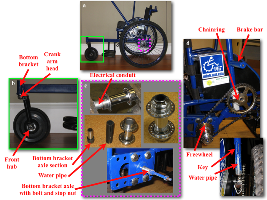 Figure 2. LFC bicycle part construction. a) All moving parts on the LFC are made from bicycle components. b) The front caster assembly. c) The rear hub and axle assembly, with hub inserts made from electrical conduit and water pipe. d) Lever coupling to drivetrain made from water pipe.
 All moving parts on the LFC are made from bicycle components, as shown in Fig. 2. This construction strategy was chosen because bicycles, as well as part suppliers and service shops, are ubiquitous in the developing world, making the LFC manufacturable and repairable virtually anywhere. By collecting or inspecting bicycle part samples in Kenya, Tanzania, Zambia, the Philippines, Thailand, Vietnam, Guatemala, and Nicaragua [11], as well as conferring with other developing country wheelchair groups [12, 13], we identified components from single-speed, steel frame bicycles derived from early 20th century safety bicycles [14, 15] as the most prevalent in the developing world and appropriate for incorporation into the LFC. These components are produced by the millions by manufactures such as Avon in India [16] and Phoenix in China [17], and sell wholesale for approximately one dollar per pound [11].
Front Caster Assembly Design
The front caster swivel in Fig. 2b is constructed from a bottom bracket assembly. To take advantage of the cotter pin coupling that fixtures the bottom bracket axle to pedal crank arms, the caster fork bridge incorporates the head of a crank arm. A steel strap wrapped and welded around the fork bridge evenly distributes torque and enables the fork to be made from 25mm OD, 1.2mm wall thickness mild steel lightweight tubing. Under a static load of 100kg, this design has a safety factor of 100 for torsional failure, calculated with the Tresca Yield Criterion [18] and a yield strength of 330MPa for 1020 steel [19].
The fork geometry (caster angle, trail) was adopted from the Worldmade chair, as was the molded rubber caster wheel. A bicycle front hub, which is pressed into the rubber wheel, serves as the caster bearing. Pressing bicycle hubs into molded rubber wheels is a process already used by local wheelchair manufacturers [13, 20], as is molding the rubber directly onto the hub [12].
Rear Hub Design
Bicycle hubs provide an ideal interface between an axle and a spoked wheel. However, wheelchair wheels must be cantilevered from the chair for handrim clearance, whereas bicycle hubs are designed to be simply supported, such as by a fork. Figure 2c depicts how a bicycle hub is used to make a rear hub of the LFC. The hubs are strengthened by first inserting one-inch electrical conduit, and then half-inch schedule 40 water pipe. Both of these materials are commonly found in hardware stores or steel companies in the developing world [21]. The water pipe is slit axially and pressed onto a section of bottom bracket axle before it is inserted into the hub. When the hub is welded and the axle section is removed, the resulting hub inner diameter forms an interference fit with a bottom bracket axle, which is used as the rear axle in the LFC. A bolt is welded to the end of the axle, which passes through the hub once the two are assembled. A stop nut welded to the bolt positions the hub correctly on the axle, and a lock nut secures the hub in place. A conventional bicycle freewheel, used to transfer power to the wheel from the LFC drivetrain, is threaded onto each hub and secured with a tack weld.
The safety factor for the rear axles was calculated by comparing loads on the LFC to those exerted on the same components when used on a bicycle. The force exerted on the bicycle pedal acts at a moment arm of 9cm away from the bottom bracket bearing; the main radial force on an LFC wheel acts at 5.5cm away from the bearing. Assuming, during an impact (such as jumping off a curb), that all inertial loads are transferred to the axles, and that the rider’s weight is approximately the same for both cases, the bending stress in the LFC axles will be 1.6X less than that in the bicycle bottom bracket axle.
Levers, Couplings, Brakes, and Drivetrain Design
The bottom of each lever is made from sections of half-inch schedule 40 water pipe, as shown in Fig. 2d. The water pipe slides into couplings on the drivetrain chainrings. The levers are keyed to align the brake bars perpendicular to the wheels. Pushing forward on the levers provides the power stroke; pulling back ratchets the freewheels on the rear hubs. The brakes are applied by pulling the levers back to approximately five degrees beyond vertical, which pushes the brake bars against the tires.
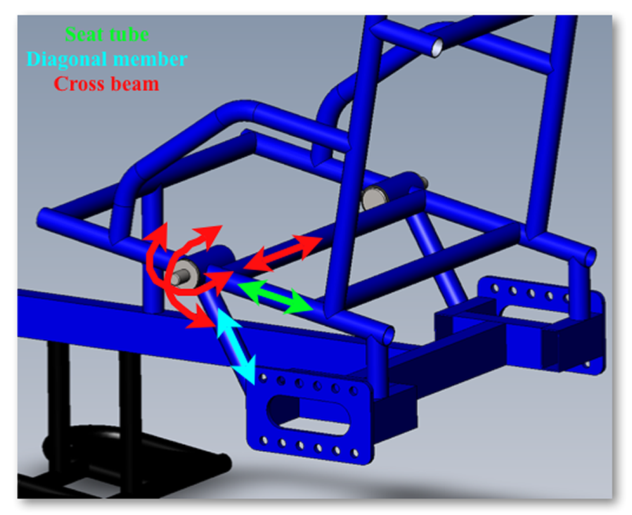 Figure 3. LFC frame members make a truss that provides a stiff support
for the lever/chainring pivot axle. Stiffness contributions of each
member are color-coded.
Figure 3. LFC frame members make a truss that provides a stiff support
for the lever/chainring pivot axle. Stiffness contributions of each
member are color-coded. The levers are made from 25mm OD, 1.2mm wall thickness mild steel lightweight tubing. The water pipe used in the coupling extends 15mm inside the lever. This increases the area moment of inertia at the bottom of the lever, where the highest moments are applied. Considering a max pushing load of 356N, corresponding to the 50% male [8], acting at 40cm from the lever pivot (25cm along the 25mm OD section of tubing), the resulting Safety Factor for the lever is two. A higher factor of safety was not sought in order to minimize the rotational inertia of the levers. Addtionally, ductile failure of the levers would not result in a catastrophic failure.
The levers/chainrings rotate on two bottom bracket axles, whose housings are welded into the LFC frame. This design reduces the rotational inertia of the levers/chainrings, which improves propulsion efficiency by minimizing inertial losses caused by accelerating/decelerating the levers when changing pushing/pulling direction. The chainring axles experience the highest non-impact loads in the LFC, due to forward and lateral pushing forces on the levers, and chain tension on the order of 1000N. To prevent deflection of the axle, which could cause the chain to derail, the axle bearing housing is built into a 3-dimensional truss within the frame. Figure 3b shows how forward and vertical deflections are mitigated via the seat tubes and the diagonal members that run from the chainring axle bearing housings to the rear wheel bolt plates. Lateral and rotation stiffness is bolstered by a cross beam that is welded to both bearing housings and runs under the seat.
Frame Loading and Material Choice
The LFC is constructed from materials commonly available in developing countries: mild steel, wood, furniture foam, and textiles. Aluminum and titanium are either unavailable, too expensive, unworkable because of the lack of appropriate welding equipment, or of unreliable quality. The highest stress in the frame occurs in the cantilevered tube that supports the front caster. Using available tubing sizes in East Africa [21], the cross-sectional geometry with the highest strength to weight ratio and safety factor of six or more (based on static loading) was identified as 25mm X 50mm rectangular box tubing with 1.2mm wall thickness. This safety factor was chosen by considering: 1) the tube would fail in bending; 2) failure could result in injury to the rider; and 3) 3X static loading on the front wheel is conservative, as impacts, such as drops off curbs, are absorbed primarily by the rear wheels [22].
TESTING AND FABRICATION RESULTS
The LFC underwent a 200,000 cycle double-drum test [23] at Whirlwind Wheelchair International in June 2009. At 99,061 cycles the left rear wheel bearing failed. Upon inspection, it was determined that the cause of failure was plastic deformation of the outer bearing race. During the production of this LFC prototype, the failed bearing race was heated red-hot from nearby welding. This most likely annealed the race, causing it to fail. After the bearing cups were replaced, the LFC prototype completed the double-drum test without incident. All of the bearings in subsequent prototypes have been assembled after welding and no further failures have been experienced.
In August 2009, the authors, in collaboration with APDK, produced eight LFC trial prototypes in Kenya, two of which are shown in Fig. 1. This exercise proved that the LFC could be completely manufactured with developing country tools and materials. The total cost per chair, including 30% overhead for labor and electricity, was $195.28, which is in the $150 to $300 price range of other locally-made wheelchairs [13, 20, 24]. Six of the prototypes were given to APDK clients for a four-month-long trial. Each LFC was custom-fit to its user, following the WHO’s Guidelines for the Provision of Manual Wheelchairs in Less Resourced Settings [25]. Each client was required to have an existing mobility aid to use in the case the LFC became unsafe or uncomfortable. The trial was approved by both MIT’s and APDK’s Institutional Review Boards.
CONCLUSIONS AND FUTURE WORK
At the time of writing this paper, the LFC was still being trialed in East Africa. None of the prototypes had experienced mechanical problems beyond tire punctures. All of the trial subjects will be interviewed during January 2010. The data collected during the trial follow-up will be used to refine and improve the design of the LFC. Complaints received thus far focus on the chair’s width and weight; the LFC’s drivetrain forces the wheels to be set out approximately 8cm beyond the width of an equivalently sized Worldmade chair, and adds about 5kg to the chair’s mass. Our future work will focus on reducing the width and weight of the LFC, such that when the levers are removed it can function indoors as effectively as a conventional wheelchair.
REFERENCES
- van der Woude, L.H.V., et al., Alternative Modes of Manual Wheelchair Ambulation: An Overview. American Journal of Physical Medicine & Rehabilitation, 2001. 80(10): p. 765-777.
- Winter V, A.G., Assessment of Wheelchair Technology in Tanzania. The International Journal of Service Learning in Engineering, 2006. 1(2): p. 60-77.
- Woude, L.H.V.v.d., et al., Mechanical Advantage in Wheelchair Lever Propulsion: Effect on Physical Strain and Efficiency. Journal of Rehabilitation Research and Development, 1997. 34(3): p. 286-294.
- Linden, W.L.v.d., et al., The Effect of Wheelchair Handrim Tube Diameter on Propulsion Efficiency and Force Application (Tube Diameter and Efficiency in Wheelchairs). IEEE Transactions on Rehabilitation Engineering, 1996. 4(3).
- Groce, N.E., Health beliefs and behaviour towards individuals with disability cross-culturally. Introduction to Cross-Cultural Rehabilitation: An International perspective 1999.
- Warner, D., Nothing About Us Without Us: Developing Innovative Technologies For, By and With Disabled Persons 1998.
- Annual Program Statement. USAID, 2003.
- Cott, H.P.V. and R.G. Kinkade, Human Engineering Guide to Equipment Design. 1972, Washington D.C.: U.S. Government Printing Office.
- Winter V, A.G., et. al, The design and testing of a low-cost, globally-manufacturable, multi-speed mobility aid designed for use on varied terrain in developing and developed countries, Paper# DETC2009-87609, in ASME IDETC 2009: San Diego, CA.
- Worldmade Wheelchair, http://www.motivation.org.uk/worldmade/ . 2010, Motivation UK.
- Conversations and transactions with bicycle part suppliers and wheelchair workshops in: Nairobi, Kenya; Dar es Salaam, Tanzania; Lusaka, Zambia; Manila, Philippines; Bangkok, Thailand; Ho Chi Minh City, Vietnam; Antigua, Guatemala; and Chinandega, Nicaragua. 2005-2010.
- Personal correspondence, http://www.whirlwindwheelchair.org/ . 2009, Whirlwind Wheelchair International, San Francisco State University, Sanfrancisco, CA.
- Personal correspondence, http://www.apdk.org/ . 2009, The Association for the Physically Disabled of Kenya, Nairobi, Kenya.
- Sharp, A., Bicycles & Tricycles: An Elementary Treatise on Their Design and Construction. 1 ed. 1896, New York: Green & Co.
- Brown, S., Articles about Old Bicycles and Parts, http://www.sheldonbrown.com/oldbikes/index.html . 1995.
- Avon Cycles, http://www.avoncycles.com . 2007, Avon Cycles LTD.
- Pheonix Bicycles, http://www.phoenix-bicycle.com/phoenixie/page/index.asp . 2007, SHANGHAI PHOENIX IMP.&EXP.CO.,LTD.
- Shigley, J.E., Mischke, C.R., Budynas, R.G., 6-4 Maximum-Shear-Stress Theory for Ductile Materials, in Mechanical Engineering Design. 2004, McGraw Hill: New York. p. 259.
- AISI 1020 Steel, as rolled, http://www.matweb.com/search/DataSheet.aspx?MatGUID=a2eed65d6e5e4b66b7315a1b30f4b391. 2010, MatWeb.
- Personal correspondence, http://kientuong.net/home.aspx . 2007, Kien Tuong Wheelchair Workshop, Ho Chi Minh City, Vietnam.
- Steel Products, http://www.doshi.co.ke/section.asp?ID=17 . 2009, Doshi Enterprises LTD, Nairobi, Kenya.
- Shigley, J.E., Mischke, C.R., Budynas, R.G., 1-11 Stress and Strength, in Mechanical Engineering Design. 2004, McGraw Hill: New York. p. 22-25.
- Wheelchairs -- Part 8: Requirements and test methods for static, impact and fatigue strengths, in ISO 7176-8:1998. 1998, International Organization for Standardization.
- Personal correspondence. Mobility Care Wheelchairs, Moshi, Tanzania, 2005.
- Guidelines on the Provision of Manual Wheelchairs in Less Resourced Settings. 2008: World Health Organization Press.
ACKNOWLEDGMENTS
Funding for this project was provided by the Hugh Hampton Young Memorial Fellowship, the MIT Public Service Center, the MIT Department of Mechanical Engineering, the MIT IDEAS Competition, the MIT Edgerton Center, the MIT Undergraduate Research Opportunities Program, the Dassault Systèmes SolidWorks Corporation, and the Clinton Global Initiative. The authors would like to thank the Association for the Physically Disabled of Kenya, Whirlwind Wheelchair International, Abdullah Munish of the Kilamanjaro Association for the Spinally Injured, Fatuma Acan from the Pan-African Wheelchair Association, Prof. Dan Frey of MIT, and Jon Pearlman from the University of Pittsburg for their collaborations, input, and guidance.
AUTHOR OF CORRESPONDENCE
Amos G. Winter, V
PhD Candidate in Mechanical Engineering
Massachusetts Institute of Technology
Phone: +(617) 312-4207
Email: awinter@mit.edu