RESNA Annual Conference - 2012

AMTAC: Adjustable Mechanism for the Transfer to Adaptive Cycles
Jayne Gavrity, Cassandra Gorman, Simon Kim, Caitlin O’Connell
University of Rochester

ABSTRACT
AMTAC
Adaptive cycling is a great activity for those who have to use wheelchairs because it offers them a social and physical outlet which can help improve their quality of life. In order to participate in cycling individuals must be transferred from their wheelchair to the hand cycle. This process is dangerous and strenuous on both the individual and the transfer assistant. The height difference between the wheelchair seat and the seat of the hand cycle makes the transfer difficult and the rear wheel of the hand cycle blocks the transfer path adding another obstacle. Our device is a lift system that goes under the rear frame of the hand cycle and allows the seat to be raised to an appropriate transfer height such that it is level with the wheelchair seat. Also, to address the obstacle of the rear cycle wheel we have made use of quick release wheels that can be easily removed and reattached once the cycle wheels are off of the ground. We have also developed a brace for the front wheel that ensures stability of the hand cycle during the transfer process. Thus, with the incorporation of our AMTAC device the transfer process from a wheelchair to the hand cycle is easier and safer.

BACKGROUND

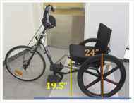
Figure 1
Adaptive sports allow for individuals who use wheelchairs to participate in athletic events and maintain a healthy, active lifestyle. For many of these sports, individuals remain in their wheelchairs, however if an individual is cycling they must be transferred from their wheelchair into the seat of the cycle and back again. The transfer process, although necessary, presents several risk to both the individuals and those assisting them with the transfer. These risks are due to the fact that there is not a clear path of transfer from the individual’s wheelchair to the seat of the cycle. Height differences and the wheels of both the cycle and the wheelchair prevent an easy transfer, as can be seen in the figure below. There are several methods and devices used for wheelchair transfer, however the preferred method for transfer to cycles is to use a slide board. This method presents the opportunity for the individual to fall during the transfer and also requires a significant amount of assistance from those aiding in the transfer which puts them and the individual at risk for injury. In 2003, more than 100,000 injuries due to wheelchair accidents were seen in emergency rooms in the United States. Out of those cases, 65-80% were the result of tipping or falling. (Xiang) The goal of this project is to develop a device that will allow for the seat of an adaptive cycle to be raised and lowered to the appropriate height during transfer in an attempt to minimize the number of injuries to individuals and those assisting.

The device we have designed will be useful to individuals who rely on wheelchairs for transportation but participate, or wish to participate, in an adaptive cycling program. It will also be useful to the individuals providing assistance during the transfer process. Table I and Table II contain the needs and wants that have been used as a guideline to developing this device. Attaining a minimum height differential between the wheelchair seat and the hand cycle seat, and eliminating the rear cycle wheel as a transfer obstacle are two of the main customer needs. The device must be able to hold and lift the weight of an individual as well as improve the safety of the transfer process for all those involved.

PROBLEM STATEMENT

Our device aims to create an environment in which the transfer from a wheelchair to a hand cycle via a slide board is safer and easier for both the individual being transferred and those assisting in the transfer.

CUSTOMER

This project was brought to us by SportsNet, which is an adaptive recreation program in Rochester, NY. We are working specifically with their adaptive cycling program and based our design requirements off of their wants and needs which can be seen below in Table I and Table II . Although these are our initial customers we believe that the AMTAC device would be a great asset to any adaptive cycling program similar to SportsNet, as well as to individuals. Table I and Table II also list our proposed testing plan to determine if all the design requirements were met. At this point only two of these tests have been completed, however they are the tests necessary to prove that the device is safe and functional and were therefore considered the most significant to development.

Table 1. Customer needs with associated metrics and testing.
Need Metric Acceptable Range Proposed Test
Ability to adjust height level of seat Length (in) +/- 8 in Raise and lower the seat to different heights.
Ability to hold and lift weight of person Weight (lb) >300 lb Test device with different weights in seat to 300 lbs.
Safety (No tipping) Weight (lb) >300 lb Test different weights at different positions until tipping occurs.
Does not tip on uneven ground Weight (lb) >300 lb Same tipping test but with device and bike set up on uneven ground.
Low manufacturing cost %Cost of bike <15% Calculation at end of project, no physical test required
Portable Yes/No Yes Survey a panel of possible users (transfer assistants).
Wheel is consistently replaced correctly Yes/No Yes How much force is needed to attach the quick release wheel


Table II. Customer wants with associated metrics and testing.
Want Metric Acceptable Range Proposed Test
Durability (used year-round or stored during winter) Time (years) > 5 years Would need to conduct long term testing after manufacturing with yearly safety checks.
Compatible with different cycle or seat models Yes/No Yes Do all related safety checks with different bike models.
Easy to use Duration of complete transfer (min) <5 minutes Time transfer with actual users after other safety criteria are met.
  # Steps to prepare for biking 1-5 Count number of steps required
  # People other than user required for transfer 1 Survey actual users once safety criteria are met.
  Force required to raise seat with user (lbs) ≤40 lbs Measure force required to raise lift with maximum weight in seat using scale. Also, measure time required to raise seat completely with or without weight.


DESIGN ALTERNATIVES

Several design concepts were considered in developing the most appropriate solution to the customer problem. To determine which idea most effectively addressed our customer needs, a design selection matrix was developed that is weighted to reflect the importance of each selection criterion. Three ideas were evaluated and compared to the current method of a slide board transfer. The design selection matrix is shown below.

  1. Pump under seat: A cylinder pump permanently installed within the hand cycle on a plate attached to the lower frame with the top of the pump attached to the base of the seat for lifting.
  2. Lift under cycle with removable wheel: This device would be completely separate of the cycle and latch onto the bottom frame of the cycle for transfer. Jacks would then lift the entire cycle so that the seat is in the correct position. This idea does not individually address the issue of the cycle wheel, so it would need to be used in conjunction with a quick release wheel or a device that allows easy removal of one of the rear wheels.
  3. Air cushion: This would involve placing an inflatable device onto the seat (whether under, over or incorporated into the seat cushion) that will inflate for the transfer process and deflate for riding position.
  Proposed Prototypes Current Method
Selection Criteria Max Score Pump under seat Lift under cycle with removable Air cushion incorporated into seat Slide board
Adjust height of seat at least 6 inches 10 10 10 10 0
Back Cycle tire is not in the way of transfer 8 8 10 8 2
Raise and lower weight of user 10 10 10 10 0
Safety: stable during entire transfer process 10 10 7 5 8
Safety: slide board is level during both transfers 10 8 10 8 3
Ease of use: time necessary for transfer 5 4 3 1 3
Ease of use: Number of helpers needed 5 3 2 3 4
Added weight to cycle is small 5 1 5 3 8
Added height to seat in riding position is small 5 3 5 3 8
Ease of installation 4 1 3 4 2
Compatible with different cycle models 4 1 3 4 2
Ease of manufacturing 8 4 6 6 4
durability 8 5 5 6 3
total 100 73 82 76 52
Rank   2 1 1 3
Continue?   N Y N N

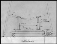
Figure 2
From the results of the design selection process, the team verified that the idea of having a lifting device underneath the frame of the hand cycle will best fit our customer needs and wants. A preliminary overall sketch of this design concept is shown below. This device will be placed under the frame of the cycle between the two back wheels. Two jacks will lift the back of the hand cycle to a position where the seat of the cycle is level with that of the wheelchair. By keeping the lifting device independent of the cycle (i.e. not built into the frame of the cycle), our design will be more compatible with different cycle models. Because the entirety of the cycle is being raised, the lifting device does not independently remove the issue of the wheel of the cycle being in the way of transfer. However, in the raised position, the wheel is no longer acting as a support for the cycle and can be removed for transfer without compromising stability. Some cycles are built with quick release axles for easy removal of wheels and will be easily used in conjunction with our lifting device. For the hand cycle models that are not currently equipped with the quick release mechanism, the proper parts can be ordered from the manufacturer so that the threaded axle can be replaced with a quick release axle. For safety, there will also be a brace for the front tire of the cycle that will prevent it from rotating during lifting. This system will be most efficient for the Sports Net organization because it will require only minimal adjustments be made on its fleet of hand cycles and because the lifting device is not connected to the cycle, they will be able to use one lifting device for all transfers.

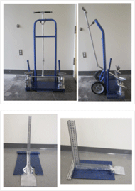
Figure 3
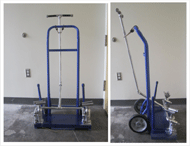
The maximum dimensions of the overall design are determined by the framework of the device, so the device must be no longer than 27’’ to fit in between the rear wheels of the cycle and have a total height of 9’’ in resting position to fit underneath the frame of the cycle. The lifting device will have two bottle jacks to lift the cycle, each equipped with a U-bar that will fit onto the frame of the cycle, which has a diameter of 1.5’’. Then, both jacks will be simultaneously pumped by a single hand bar until the cycle seat is in the desired position for transfer, at which point one of the rear wheels can be removed. After the user has been transferred, the wheel is replaced and jacks are lowered smoothly into riding position and the lifting device is removed from the cycle. The final prototypes that we developed can be seen below. The top image is of the lifting device that goes under the rear cycle frame and the bottom image is the brace that holds the front wheel in place during the transfer process.

RESULTS

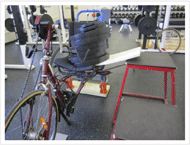
Figure 4
The device was prototyped and, once determined to be functional, testing was performed based on the customer needs listed in Table I, as well the proposed tests for each specification. The tests that have been accomplished thus far are those for raising and lowering the seat with 300lb on it and those for tipping when 300lbs was placed at different locations along the slide board. Pictures of these two tests can be seen below.The device was able to pump 300lb with the same amount of effort needed when no weight was present. Also, no tipping occurred during testing when 300lbs was placed in the following locations:

  1. Where the slide board and the wheelchair seat overlap
  2. In the middle of the slide board.
  3. Where the edge of the hand cycle seat and the slide board overlap.
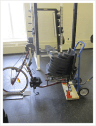
Figure 5
The slide board was placed in two orientations; perpendicular to the edge of the hand cycle seat and at a 45 degree angle to the edge of the hand cycle seat. The final variation used during this testing was the height that the hand cycle was raised. There was not tipping of the hand cycle or the device during any of the possible combinations of weight location, hand cycle height or slide board orientation. Thus, we concluded that our device is stable enough to use as a transfer mechanism.

FUTURE IMPROVEMENTS

Design Team
Moving forward with this design the most prominent part that needs improvement is the release mechanism. Although attachments have been made to aid in releasing the pumps, the two bottle jacks are still released separately. This is satisfactory for the time being, however as development continues a coupling mechanism for the release of both bottle jacks would need to be designed. Also, a way to attach the front brace to the rear pump system will be designed to allow for easy transportation and decreased storage space.

REFERENCES

Xiang, H., Chany, A., & Smith, G. (2006). Wheelchair Related Injuries Treated in US Emergency Departments. Injury Prevention , 8-11.

ACKNOWLEDGMENTS

Dr. Amy Lerner

Dr. Scott Seidmen

SportsNet – Anita O’Brien and Johnny Fahner-Vitelic

Art Salo