THE AJR SYSTEM: AUTONAVIGATING POWER MOBILITY FOR SCHOOL AND OFFICE
Mark I. Bresler, MBME, ATP, PE
Squier Assistive Technology Center - Woods Services Langhorne, PA 19047 USA
INTRODUCTION
Working with other therapies, the Assistive Technology department has tried to place three clients in power mobility and increase their independence. Due to control and vision problems, the teams have not found commercially available solutions for these clients. Taking another look at the problem, it was realized that a large portion of their travel was between a small number of places. As a student, these include their classroom, the art room, music room, gym, therapies, and the cafeteria.
This might be the case in many school or office settings.
BACKGROUND
Improving technology can increase the possibilities of what an individual, especially those with disabilities can do in their daily lives. As detailed by Woods and Watson1, more sophisticated wheelchair controllers allowed smoother control of speed and direction. Their history made no mention of expectations that even more complex electronics could be useful to possible users unable to navigate using a standard joystick. Their paper did use the term “socio-technical” to describe how power mobility advances involve progress on social and political fronts as well as technical.
Nelson et al2, proposes that before research and development of smart wheelchairs progresses, we take a step back and ask some fundamental questions about what we hope to accomplish. The paper discusses obstacle avoidance, including open stairwells, and raises questions about complexity and reliability.
Jaffee3 at the Palo Alto, CA VA, describes a power wheelchair control system using two sets of ultrasonic sensors, one to determine head position and orientation, the second for wheelchair to wall distance and orientation. The system allowed head movement to control speed and direction, and wall tracking to reduce the directional corrections a wheelchair requires to stay in a straight line.
Simpson et al4 is another example of VA research into smart wheelchairs, where devices from four manufacturers were fitted with sensors and additional computational capabilities. These prototypes have not yet yielded a commercially available product. In the absence of off the shelf devices, construction of simple systems to auto navigate were investigated.
Work with a Heathkit HERO 2000 robot proved it is possible to auto navigate in the main school building using sonar distance ranging systems. This knowledge and techniques were transferred to control a Turtle Trainer5, a power mobility platform capable of moving a manual wheelchair and a user. For project development purposes, a temporary seat added. Once finished, the seat will be removed and the forward platform available for a client’s wheelchair.
To speed development, a microprocessor based hardware and software system revised from the Tamara System was used.6
METHODOLOGY
The Assistive Technology Department is located in a single story educational building, constructed of cinder block walls with straight 8' wide hallways. Moving between rooms involves a series of straight moves and 90 degree turns. Six sonar units determine distance measurements, which are used for three purposes:
1) Obstacle detection: The AJR system will stop if there is an obstacle close by in the direction of movement.
2) Course correction: A feedback system was written in software to help maintain a desired distance from a wall. This subsystem allows the power mobility device to start a travel segment without being perfectly parallel to the wall, will correct for casters not being in the direction of travel, and steers around a fire extinguisher jutting into the hallway.
3) Movement segment end detection: For straight segments, a multiple of the desired distance to the wall is used to sense the end. To reduce false triggers, multiple readings are used.
Six basic movements: forward, forward left, forward right, left, right and reverse are used. End conditions include: forward until wall, forward until left wall ends, forward until left wall starts, forward until right wall ends, forward until right wall starts, right turn until right forward and right rear clearances are equal, and others. The system can track and correct direction to keep a desired clearance from one wall while using the opposite wall for end conditions. Moving between rooms involves a sequence of segments. For example, going from the Assistive Technology Department to the Senior Occupational Therapist's office requires:
- FUW Forward Until Wall (Cross hallway)
- R90T Right 90 degree Turn
- TLWULE Track Left Wall until Left Ends
- PM-STOP Power Mobility Stop
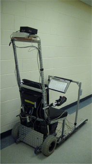 Picture 1: AJR System Test setup d
The above example is subroutine ATJOE (Joe is the Senior Occupational Therapist). Future versions of the software will remember the system’s current location; therefore the user will only need to enter the desired destination.
Note that traveling from Joe's office to the AT department is not the reverse sequence. Because of classrooms along one side of the hallway, the sequence is:
- FUW Forward Until Wall (Cross hallway)
- TLWULE Track Left Wall until Left Ends (Move to start of C-5 Classroom entry hall)
- FULWS Forward until Left Wall Starts (Move to end of C-5 Classroom entry hall)
- TLWULE Track Left Wall until Left Ends (Move to start of C-8 Classroom entry hall)
- FULWS Forward until Left Wall Starts (Move to end of C-8 Classroom entry hall)
- TLWULE Track Left Wall until Left Ends (Move to start of C-9 Classroom entry hall)
- FULWS Forward until Left Wall Starts (Move to end of C-9 Classroom entry hall)
- TLWULE Track Left Wall until Left Ends (Move to start of AT entry hall)
- PM-STOP (Power Mobility Stop)
 Picture 2: Microprocessor to Power Mobility Control Circuit d
Current programming and sensors require that the AJR system be pointing within approximately 20 degrees of the desired direction of travel.
A Motorola 68HC11 microprocessor with a 64 KB address space and FORTH programming language was used as a controller.
The initial concept was to emulate directional switch inputs for a power mobility device. Due to tracking errors, finer directional control was desired and circuitry was developed to imitate an Invacare Mark II joystick.
RESULTS
 Picture 3: Microprocessor to Power Mobility Control Circuit installed in Joystick d
The prototype has successfully auto navigated from the AT department to an office down the hallway. Work continues on the wall following algorithm in order to reduce the deviations from a straight line.
DISCUSSION
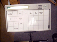 Picture 4: Prentke-Romich DeltaTalker used as a 32 location input device d
Further tests will be conducted to determine the system’s ability to operate in a busy hallway. This includes tests to better characterize object detection distances, and maneuvering and stopping distances. Areas for development include the ability to change course in mid path, and automated turn around. It is hoped this project will increase some client’s independence. While the auto navigating feature will not assist outside the building or within a room, it might be an effective method to allow clients greater control of their mobility. It is hoped this technique will prove to be another piece of the puzzle in providing mobility solutions for others needing navigational assistance.
REFERENCES
-
Woods, B., Watson, N. : A Short History of Powered Wheelchairs, Assistive Technology Volume 15.2/ Winter, 2003, page 164
- Nelson, P, Verberg, G., Gibley, D., Korba, L. The Smart Wheelchair: A discussion of the Promises and Pitfalls, RESNA, 13th annual conference, Washington DC, 1990, page 307.
- Jaffe, D. RESNA, Smart Wheelchair: RESNA 4th annual conference, Washington DC, 1990, page 91.
- Simpson, R., LoPresti, E., Hayashi, S., Nourbakhsh,I, Miller, D., : The Smart Wheelchair Component System, JRRD, May/June 2004, page 429
- Bresler, M., “Turtle Trainer: a Way to Evaluate Power Mobility Readiness" RESNA, 13th annual conference, Washington DC, 1990, page 399.
- Bresler, M., “The Tamara System: Integrated Control of Mobility, Communication, and Environment" RESNA, 12th annual conference, New Orleans, LA, 1989, page 314.
ACKNOWLEDGEMENTS
The author would like to thank the following for assistance:
Charlie Crist: for fabrication of the temporary seat and project enclosures.
Marisa Martin: for giving pointers on data analysis.
Squier Assistive Technology Fund for purchasing parts used in this project.
Author Contact Information:
Mark I. Bresler, MBME, PE
Assistive Technology Specialist
Woods Services
PO Box 36, Langhorne, PA 19047
(215) 750-4112 voice, (215) 750-2987 fax mbresler@woods.org , www.woods.org