Exploring the Relationship of Rolling Resistance and Misalignment Angle in Wheelchair Rear Wheels
Jonathan Vander Wiel, Boice Harris, Carl Jackson, Norman Reese
Interdisciplinary Mobility Lab, LeTourneau University, Longview TX
ABstract
To address the humanitarian problem posed by millions of people in the world that need wheelchairs, non-profit organizations design, manufacture, and distribute low cost wheelchairs. These wheelchairs sometimes have camber or toe wheel misalignment after manufacturing or long-term use. With marginal health, wheelchair users are greatly impacted by greater physiological cost that may result from such wheel misalignment. An instrumented cart was developed to measure the rolling resistance of various wheels under a variety of weights and camber/toe alignments. The resulting data collected from the system showed that rolling resistance increases parabolically with greater toe misalignment and is minimally affected by camber. Rolling resistance was found to increase 25.5% with 1° of toe in or out misalignment. These results underscore the importance of proper wheel alignment in manufacturing and wheelchair setup.
BACKGROUND
The World Health Organization estimates that 20 million people in the world are in need of wheelchairs [1]. The majority of these people live in low resource settings where access to modern efficient wheelchairs is beyond reach. Non-profit organizations around the world raise funds and build wheelchairs for these needs. Because these wheelchairs are paid for by charitable donations and intended for use in low resource areas, organizations must balance wheelchair quality, all terrain capabilities, ease of maintenance, and a target cost of $100-$300. These organizations are continuously balancing the trade-off of maximizing the number of people they can assist versus the quality of the wheelchair provided. Understanding rolling resistance as a function of wheel misalignment will allow manufacturers to develop and prioritize manufacturing processes that minimize wheel misalignments which waste the user’s energy.
A small sample of wheelchairs, at a school for students with disabilities in Kenya, was evaluated for toe misalignment in 2015 in conjunction with this study. Wheel alignment of 51 low-cost wheelchairs was measured. In the interest of space, that study will not be described here in detail. The critical conclusion was, amongst a normally distributed group with a mean misalignment of 0.20°, 53% of those chairs in use had greater than 0.5° toe, and 24% had greater than 1° toe in their rear wheel alignment. If that much wheel misalignment is pervasively common, then the resulting physiological cost clearly needs to be understood.
Wheelchair rolling resistance has previously been considered using primarily human metrics by researchers such as Hilbers [2], and Perdios [3]. These metrics included oxygen consumption, heart rate, mechanical efficiencies, and arm abduction angles. Testing the rolling resistance of individual wheels, separate from the wheelchair system, provides a repeatable quantified metric that is not subject to the wide variety of individualized wheelchairs. The rolling resistance force is also a metric needed for the ongoing development of a comprehensive mechanics model of wheelchair usage seen in foundational models such as Hofstad’s model [5]. Mathematical models have been produced by Suaret that predict rolling resistance relative to factors such as floor material, wheel type, and tire pressure. [4]. This study does not seek to change or expand these models, but rather observe the importance of wheel misalignments, a factor not considered in these models.
Rolling resistance force, FRR is modeled simply by Equation 1. This equation states that the rolling resistance force, FRR, equals the coefficient of rolling resistance, µRR, multiplied by W, the weight on the wheel.
(1)
The force being applied to keep the wheel rolling at a constant velocity is equal to the force of rolling resistance.
Resistance data is often collected by means of a coast-down test with a loaded wheelchair [6]. In these tests, a large drum, with a large moment of inertia, is spun at a constant angular velocity, then disengaged and the angular velocity is measured as a function of time, which can be used to derive the rolling resistance force [7]. Such coast-down tests require expensive fixturing and development to characterize the operating characteristics of the drums at different loads and velocities [9]. Similar limitations have been noted in testing of automobile rolling resistance [10]. A new test system was developed to isolate specific rolling resistance measurements at constant velocities and wheel alignment angles.
TESTING SYSTEM
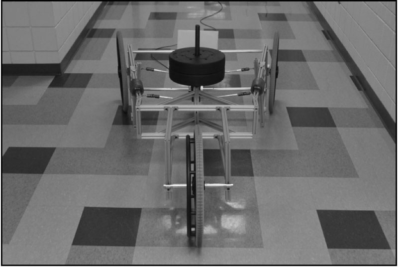
Misalignment Cart
The misalignment cart was constructed with an aluminum T-slot frame to mount three wheelchair wheels with an applied weight that would be equally distributed between the three wheels (Figure 1). Joints and control arms allow the front two wheels to be rotated and locked in an equal amount of camber or toe in/out. The rear wheel always maintains a straight alignment. For all the tests described, a 22-inch non-pneumatic tire was used on polished tile floor.
Tow Control
The CARRT is towed by a lightweight steel cable wrapped on a plastic drum which is turned by a three phase AC motor. The motor is controlled with a variable frequency drive (VFD) that allows the cart to be pulled at any chosen velocity. The VFD ramps up to test velocity of 0.5 m/s at a gradual rate to minimize overshoot.
Instrumentation
Data Analysis
The data was analyzed using Matlab software for data selection, outlier detection/removal, and force and velocity calculations. The data was then run through outlier detection program based on chauvenet’s criterion used to detect and remove outlier data points. The resulting filtered data was averaged to find the force over the run. Curve fitting was performed using Microsoft Excel.
Testing Procedure
After setting up the cart with the specific alignment desired and wheel loading equivalent to a 130lb user with a 60/40% loading distribution, the cart was pulled at a constant velocity of 0.5m/s.
Validation
The approach taken to validate results was to replicate a linear increase in rolling resistance as weight was applied. The cart was configured with no misalignment in either camber or toe, and weight was progressively added. This relationship is also supported by similar studies by Grappe [11] and Kauzlarich [12]. The data collected fit closely with the linear relationship expected.
RESULTS
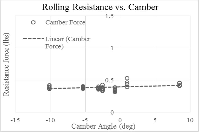
Camber Misalignment

Toe-in/out Misalignment
Rolling resistance values with toe-in/out misalignments were calculated at 9 points between 3 degrees of toe in and 10.5 degrees of toe out in Figure 5. The data shows that for angles of toe-in/out, rolling resistance increases as a symmetric second-order polynomial. At high angles of toe-in/out misalignment, it appears that wheel skid becomes an increasingly large factor. This results in the discontinuity in the function at around 5° which puts a sharp bend in the curve. While these large angle relationships are interesting from a mechanics modeling perspective, toe in/out beyond 3 degrees is extreme and is not of practical significance. As such, the discontinuity at 5 degrees was not evaluated further.
DISCUSSION OF RESULTS
The implications of the toe-in/out relationships have direct meaning for both manufacturers and clinicians that observe the long term maintenance condition of wheelchairs. Table 1 lists the increase in rolling resistance as a percent increase over rolling resistance with no misalignment.
| Toe-in/out angle | Percent increase in Rolling Resistance |
|---|---|
| 1° | 25.5% increase |
| 2° | 96.3% increase |
| 3° | 212% increase |
| 4° | 374% increase |
| 5° | 580% increase |
Since these values of rolling resistance apply to single wheels, a 1° toe angle on both rear wheels will not result in 25% increase in total effort to propel the wheelchair. The castor wheels will have their own independent contribution to the rolling resistance of the entire wheelchair. While the castors will typically have more rolling resistance per pound of force because of their smaller diameter, they usually carry less weight than the rear wheels. While many factors affect rolling resistance of an entire chair, it’s clear the increased resistance of wheels with 1° to 2° toe alignment would result in a significant increase in the physiological load on the user or attendant. This effort not only is wasted on propulsion, but the skidding effect of wheel misalignment vastly speeds tire wear.
LIMITATIONS
The rolling resistance tests in this study all utilized a single type of 22-inch non-pneumatic tire used by Hope Haven International for their wheelchairs. More studies are needed with other types of non-pneumatic and pneumatic tires. Age of the tire and tread wear may also affect the results. Wheel bearings and frame rigidity may also play a part. Furthermore, different surfaces such as grass or dirt may be more compliant and may lessen the impact of toe misalignment. Finally, additional studies are necessary with a variety of wheels to show how the rolling resistance is impacted by different types of tires and wheel diameters.
CONCLUSION
While the effort to propel a wheelchair is a combination of factors such as biomechanics, wheelchair component design and configuration, and rolling surface, this study shows a major consequence of wheel misalignment. Most wheelchair users and attendees do not have physiological reserves to waste or money to spend on tires that wear out too soon. In the spectrum of priorities that manufacturers must balance, ensuring proper wheel alignment should be a low cost improvement with high rewards. Additionally, design guidelines should take into account the strong negative impact of wheel misalignment, and encourage designs that minimize wheel misalignment over the life of the wheelchair.
REFERENCES
[1] Armstrong W. et. Al. “Guidelines on the Provision of Manual Wheelchairs in Less Resourced Settings”. World Health Organization. 2008
[2]Hilbers, P. et al. “Effects of Wheelchair Design on Metabolic and Heart Rate Responses During Propulsion by Persons with Paraplegia” Journal of the American physical therapy association 67 (1987) 1355-58.
[3] Perdios, A. et al. “Effects of camber on wheeling efficiency in the experienced and inexperience wheelchair user” Journal of rehabilitation research and development 44.3 (2007) 459-466.
[4]Sauret, Christophe, et al. “Assessment of field rolling resistance of manual wheelchairs.” Journal of Rehabilitation Research & Development 49.1 (2012): 63-74.
[5]Hofstad, Patterson. “Modelling the propulsion characteristics of a standard wheelchair.” Journal of Rehabilitation Research 31.2 (1994): 129-137.
[6] Kwarciak, Andrew M., et al. "Evaluation of wheelchair tire rolling resistance using dynamometer-based coast-down tests." Journal of rehabilitation research and development 46.7 (2009): 931-38.
[7] Salaani, M., et al. “NHTSA tire rolling resistance test development.” National Highway Traffic Safety Administration (2006): Paper 09-0300
[8] Veeger, D. et al. “The effect of rear wheel camber in manual wheelchair propulsion.” Journal of rehabilitation research and development 26.2 (1989) 37-46.
[9] Tan, X et al. “Measurment of Dynamic Rolling Friction in Linear Microball Bearings”. Journal of Dynamic Systems, Measurment, and Control vol.128: pp. 891-898
[10] Redrouthu, B.M., and S. Das.” Tyre Modelling For Rolling Resistnace”, Masters Thesis, http://publications.lib.chalmers.se/records/fulltext/200040/200040.pdf
[11] Grappe, F., et al. "Influence of tyre pressure and vertical load on coefficient of rolling resistance and simulated cycling performance." Ergonomics 42.10 (1999): 1361-1371.
[12] Kauzlarich, J. J., and J. G. Thacker. "Wheelchair tire rolling resistance and fatigue." Journal of rehabilitation research and development 22.3 (1985): 25-41.