Vinod K. Sharma1, MS and Richard Simpson1, 2, PhD, ATP
1Department of Rehabilitation Science and Technology, University of Pittsburgh
2Human Engineering Research Laboratories, VA Pittsburgh Healthcare System
Abstract:
A smart wheelchair requires short-range high-resolution sensors. Range finders using laser triangulation fulfill these requirements but they face the additional challenge of operating in bright sunlight while remaining eye-safe. The laser “line striper” described in this paper achieves all these requirements without the need of expensive components.
Keywords:
Range finder; structured light; infrared laser; smart wheelchair.
Introduction:
 |
 |
Investigators at the University of Pittsburgh are developing two intelligent mobility aids that provide navigation assistance to individuals who find it difficult or impossible to operate “standard” wheeled mobility devices. The Smart Wheelchair Component System (SWCS) for power wheelchairs [1] and the Smart Power Assist Module (SPAM) for manual wheelchairs [2] use sensors to identify and avoid obstacles and drop-offs (e.g., stairs, curbs, potholes) in the environment. Investigators evaluated a laser “line striper” for potential use by the SWCS or the SPAM.
Background:
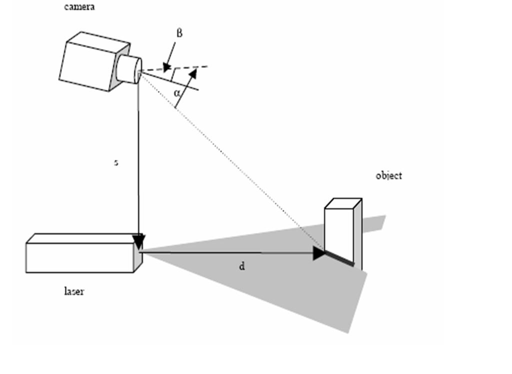
Figure 1 illustrates how a line striper works. A laser is used to create a beam of light that is focused in one axis and fanned in the other to produce a plane of light [3]. A video camera is placed at a known distance from the laser and observes where the light intersects objects.
The raw data received by the camera are the pixel intensity values in image, representing the light intensity of the scene. The first step is to identify which pixels correspond to the line projected by the laser. In the absence of background, this could simply be done by applying a threshold above the noise level. In a configuration where the centre of the camera is directly above the origin of the laser (as shown in Figure 1) there is a one-to-one correspondence between the columns and b. There is only one position in each column which corresponds to the line. Therefore we identify the line as the pixels with maximum intensity in each column above a preset threshold. To get from the pixels to the external coordinates we determine the internal parameters of the camera [7] and thereby the undistorted image coordinates. Next, the geometric relationship between the camera and the laser plane is measured. It is then possible to calculate the homology between the image plane and the laser plane.
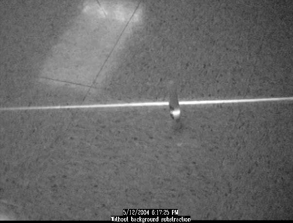
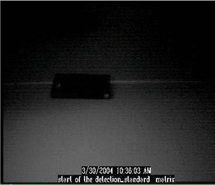
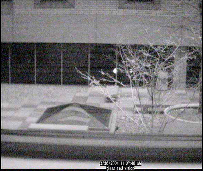
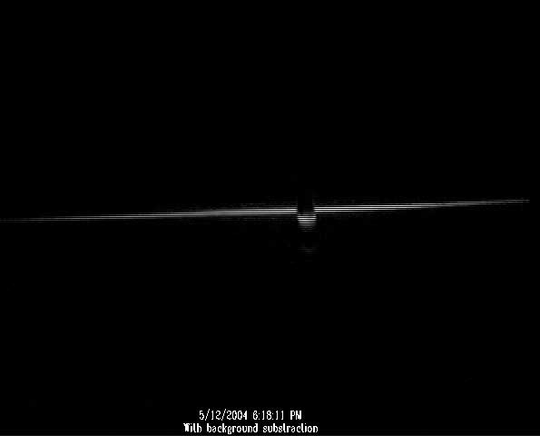
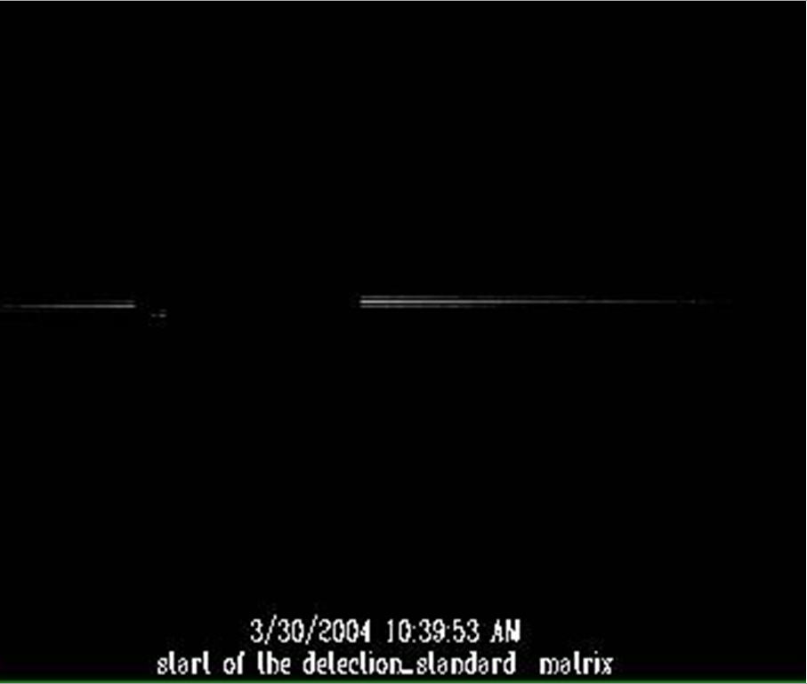
The laser used in our research (shown in Figure 1) emits a line of 60º length and 0.4º thickness, producing a light at a distance of 2.3 m that is many times less intense than sunlight. In order to calculate distances, the “background” (i.e., everything in the image that is not the laser stripe) is removed from the image captured by the camera. Each pixel in the image corresponds to a fixed distance from the camera, and the laser stripe indicates which pixels “contain” an object. Discontinuities in the laser stripe indicate changes in depth, caused either by an obstacle or a drop-off. Figure 2 shows the background subtraction process for materials with surfaces that reflect or absorb light.
| field of view (degrees) | 30 | 55 | 105 |
|---|---|---|---|
| Angular resolution (degrees) | 0.05 | 0.09 | 0.16 |
| Maximum range (cm) | 700 | 520 | 300 |
| 2-meter resolution (cm) | 1.4 | 2.6 | 5.0 |
Table 1 shows the ranges and resolution of the line striper for camera lenses with different field of view sizes . The angular resolution can be thought of as the “width” of each pixel, and is measured as the angle formed with the camera at the vertex and points in space corresponding to the top and bottom edges of the pixel. The angular resolution is the minimum distance in the real world that can be distinguished by laser image. The maximum range is the maximum distance at which a target with good reflectivity (paper) is still visible to the camera. The 2-meter resolution is the real-world length represented by each pixel in the image of an object that is 2 meters from the camera.
 |
 |
 |
 |
 |
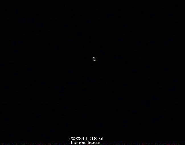 |
| A 2.2cm thick pen at a distance of 220 cm from the camera. | Black surfaces absorb the laser light. | Glass (transparent surface) allows the light to pass through. |
Methods :
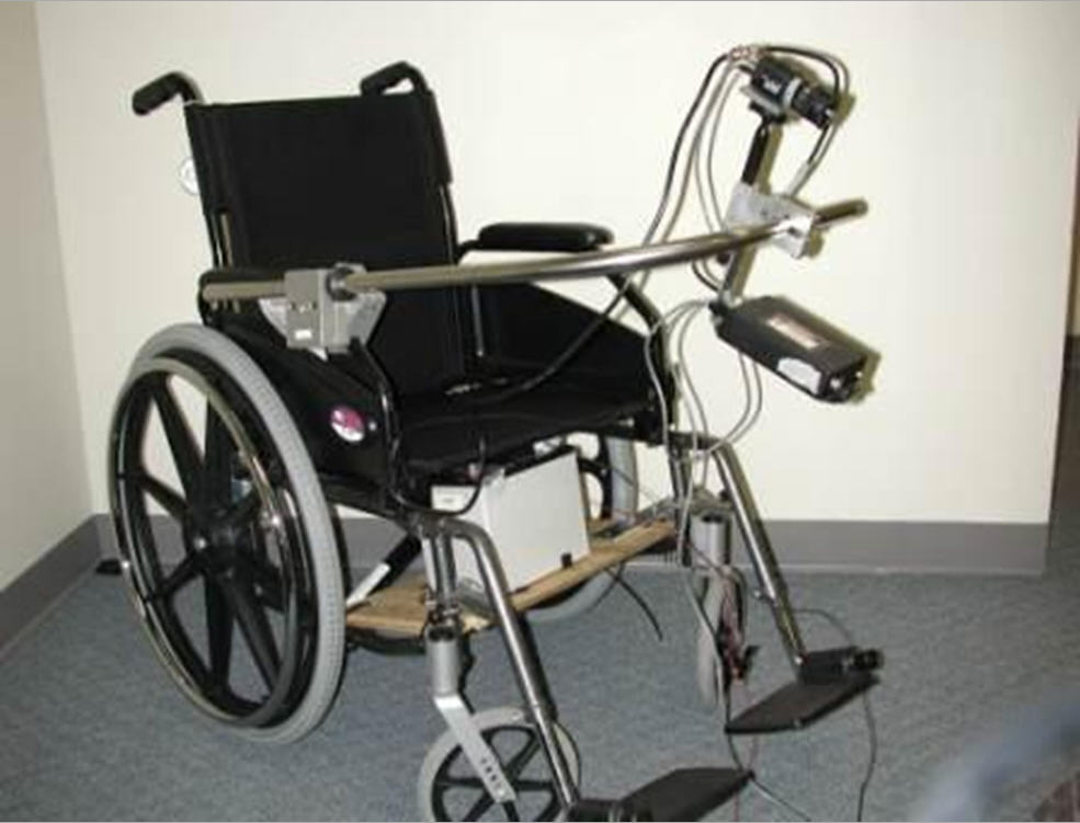
A series of tests were performed on a line striper mounted on a manual wheelchair (see Figure 2). The laser used Gallium-Arsenic (GaAs) laser diodes because they are relatively inexpensive and have a wavelength of approximately 900 nm, which is a good compromise between reduced sensitivity of the camera and increased eye safety [6]. A video camera with a high sensitivity in the near IR and a fast shutter [4] observed where the light intersected objects. It should be noted that the minimum and maximum detection distances are determined, in part, by the values of S and α. During testing, S (see Figure 1) was set at 36 cms, and α was set at 10°. The field of view of the camera lens was 55 degrees.
The accuracy of striper was evaluated using a piece of sheetrock that was painted black, a white marker board, and a section of green carpet. The sensor was initially positioned one meter from the obstacle at different angles, then moved further away from the obstacle until the camera could no longer see the object (i.e., the intensity of laser light reflected by the object is too weak to be seen by camera). This distance between the striper and the object was recorded as the maximum detection distance. This test was repeated at seven different angles for each material.
| Actual Dist. | -20° | White Surfaces(0°) | 20° | -20° | Black Surfaces | 20° | -20° | Carpet | 20° |
|---|---|---|---|---|---|---|---|---|---|
| 100 | 91 | 97 | 92 | Laser can not be reflected | 97 | Laser can not be reflected | 91 | 96 | 92 |
| 125 | 117 | 120 | 117 | 120 | 118 | 122 | 117 | ||
| 150 | 144 | 148 | 142 | 148 | 140 | 148 | 141 | ||
| 175 | 168 | 170 | 168 | 170 | 168 | 169 | 169 | ||
| 200 | 189 | 196 | 192 | 196 | 191 | 200 | 192 | ||
| 225 | 215 | 220 | 219 | 220 | 218 | 221 | 219 | ||
| 250 | 240 | 244 | 238 | 244 | 240 | 244 | 240 | ||
| 275 | 260 | 267 | 260 | 267 | 260 | 269 | 260 | ||
| Average Error | 4.03% | 1.96% | 3.42% | 2.78% | 3.61% | 1.41% | 3.36% |
Results:
The results of the experiment are shown in Table 2. Note that the laser striper was unable to see the black sheet rock when offset by as little as 20 degrees. At 0 degrees, the average error for the black sheet rock was 2.78 %. The average error for white surfaces was 1.96% at 0 degrees, 4.03% at -20 degrees and 3.42% at +20 degrees. The average error for green carpet was 1.41% at 0 degrees, 3.61% at -20 degrees and 3.36% at +20 degrees.
Some of the measurement error for all surfaces was due to lens distortions at the edge of the image. Black surfaces are only visible at 0 degrees offset because the maximum intensity of the laser is in the middle of the image, so a small amount of laser light remains visible when the laser and camera are perpendicular to the object.
Discussion :
The laser line striper is an effective range finder with an angular resolution of less than 1º and a maximum range of a few meters. The line striper can be configured for a wide range of angular coverage and is eye-safe when it is appropriately packaged. Further improvement of the laser striper would result from a more effective background subtraction method, which would eliminate external natural and artificial light. We intend to investigate more geometric configurations like increasing coverage to more than 180º and using multiple lasers, fired at different times and at different angles to allow 3D coverage [5].
References :
- LoPresti EF, Simpson RC, Miller D, Nourbakhsh I. (2002). Evaluation of Sensors for a Smart Wheelchair. Proceedings of the RESNA 2002 Annual Conference. pp. 166-168.
- Simpson RC, LoPresti EF, Hayashi S, Guo S, Ding D, Cooper RA. Smart Power Assistance Module for manual wheelchairs. In: Simpson RC, editor. International Conference on Assistive Technology for People with Disabilities (RESNA); 2003 19-23 June; Atlanta, GA: RESNA Press; 2003.
- Thorpe, C., Clatz, O., Duggins, D., Gowdy, J.,MacLachlan, R., Miller, J.R., Mertz, C., Siegel, M., Wang, C., and Yata, T., Dependable Perception for Robots. Proceedings of International Advanced Robotics Programme IEEE, Robotics and Automation Society, Seoul, Korea, May, 2001.
- Yoshida, K., Hirose, S., Laser triangulation range finder available under direct Sunlight, Proceedings of International Conference on Robotics and Automation, 1988, 1988 IEEE, pp. 1702 - 1708 vol.3.
- Bursanescu, L., Bursanescu, M., Three-line high power three-dimensional sensor, Proceedings of the SPIE - The International Society for Optical Engineering, vol.3313 p. 105-114.
- American National Standards Institute, Inc., American National Standard for the Safe Use of Lasers, Z136.l-1993, The Laser Institute of America, 1993. (ANSI Z136.1-1993), p. 31,32,41,42
- Camera Calibration Toolbox for Matlab®, http://www.vision.caltech.edu/bouguetj/calib_do c/index.html .
- C. Mertz, J. Kozar, J.R. Miller, C. Thorpe, Eye-safe Laser Line Striper for Outside Use. IV 2002, IEEE Intelligent Vehicle Symposium, June, 2002