Accessible User Interface Development: Process and Considerations
Dianne Goodwin, Nicholas Lee, Martin Stone, Daniel Kanitz
BlueSky Designs, Inc.abstract
The goal of user interface design is to provide intuitive and easy to use controls for devices. Interfaces for consumer goods are typically designed for people to control with their hands, though in recent years, this has expanded to include eye, voice and gestures. Access by people with disabilities is not usually considered.
In designing accessible device interfaces, end users with a range of physical attributes, using alternate access methods and controls must be considered. For individuals with limited access options, an interface which can utilize their existing controls is preferable. The device must also be accessible to family members and attendants as needed. Since others may be unable to use the person’s controls, an alternate interface must be available to access and set up the device.
This paper addresses design considerations and methods involved in developing accessible interfaces for a powered mounting and positioning device used on wheelchairs and other locations. Due to the modular nature of the design—ranging from a single joint to multi-joints, and the need to provide others a means of controlling the mount, two different interfaces were developed. (3,4)
related technology
Assistive devices and everyday technology like smart phones, tablets and smart homes must be considered. Power wheelchairs, speech devices and computers allow alternate means of access and offer different output modes, where the same controls operate other devices via environmental control or wireless signals.
Current wheelchair-mounted robotic arms (WMRA) focus on using manipulators to reach, grasp and perform hand-like tasks. They cannot support more than a 2.5-3 pound load and their interfaces are complex. (1,2)
modular powered mounting system
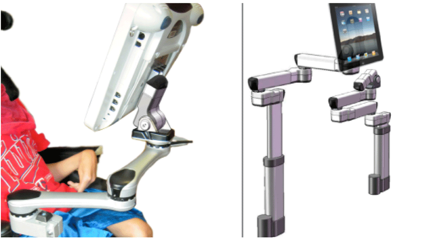
The user interface is operable by people with and without disabilities. The accessible controls allow individuals to perform key functions: program specific target positions; move to the positions, with all joints moving concurrently; create “levels”—sets of target positions for specific devices; and adjust individual joints.
The power mount is easier to maneuver than current WMRAs, with its target positions, simpler controls and ability to adjust individual joints. Each joint has a single degree of freedom. Joints provide horizontal rotation or, if reoriented, tilt. A linear actuator results in vertical or horizontal translation. For ease of description in this paper, each actuator is referred to as a “joint”.
user interface design and development methods
Determine User Interface design requirements
User access to the power mount is accomplished in a number of ways: via alternate switches plugged into the End Cap or Control Pad; wireless switches; and wireless options such as Bluetooth or ad-hoc networks via smart phones, tablets and computers.
The Single Joint is controlled via the End Cap or a wireless switch. With the Multi-Joint system, there are two different User Interfaces: the End Cap and the Control Pad. The End Cap is required for all systems, since it serves as the power supply and connection terminal.
In both Single and Multi-Joint systems, attendants can turn the system on and off and perform functions such as moving a joint, stopping it and saving set positions, using the End Cap keypad or the Control Pad. Positions are saved using a press-and-hold action once in a target position, akin to a car radio. The Control Pad is accessed via touch, controls plugged into the End Cap or Control Pad, or wireless options including smart devices.
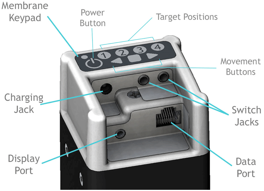
Even the simplest of powered mounting systems requires affordances for various inputs, outputs and connections: power supply, on-off button, input switches for the end user, power cable from the End Cap to the powered mount, connector for a possible display, and hard-wired or wireless data transmission. The power source can be the wheelchair, an A/C power supply, or a rechargeable battery.
The resulting design is the End Cap, shown in Figure 2, which serves as a connection hub. The printed circuit boards (PCB) within the End Cap includes a microcontroller to manage inputs and outputs, power and charging circuit, switch inputs, and data transmission. It includes a built-in membrane keypad for use by attendants. The PCBs incorporate connectors to accommodate all of the above.
Feedback:
Movement: the joint rotates or arm moves in response to a selection
Visual: joints light up to indicate it is active or lights as one scans; joint color provides troubleshooting information; display is the primary visual feedback; colors change as you scan; screens and icons change as selections are made; joint release icon when disengaged.
Auditory: the noise of the motor; auditory feedback when scanning (optional); sounds may alert them to look at the display.
End Cap: Switch operation and behaviors
Single Switch, Switch 1. Toggle Direction
Press switch. Joint moves while switch is down; stops when let up; next hit, other direction
Single Switch, Switch 2. Go to Targets
Press and release switch. Joint goes to a target position. Press and release. Joint goes to position 2. As Joint is moving, press to stop. Next hit goes back to the prior position.
Two Switches, Direction-specific
Press and hold switch. Stops when released. Second switch is different direction.
Two Switches, Two joint operation
One switch controls one joint; one controls the other. Mode of operation is selected by pressing a specific numeric sequence on the keypad.
Option 1: two Single Switches, Toggle mode
Option 2: two Single Switches, Target mode
Methodology:
Technical development
End Cap Design:
The End Cap was conceived as a means of providing one point of entry for all connections, while protecting the plugs and cables from impacts and managing cords. SolidWorks was used to design the End Cap and lay out physical components on the Printed Circuit Boards.
An internal End Cap Bracket provides for a secure attachment to the extrusion. The End Cap can be reoriented on the square extrusion which houses the battery. This allows flexible positioning, easier visual and physical access and weather protection when used outdoors.
The End Cap’s resistive membrane keypad can control the power mount. The white on black color scheme offers high contrast for visual access. Its 8 keys include an on-off button, 4 programmable position keys, and 3 movement keys. A capacitive touch keypad was considered, but rejected. Testing showed too much “bleeding” of signals across keys when activated. In addition, some testers rejected the idea of a capacitive keypad, as it could not be activated by a mouth stick or pointer.
Early Stage Usabilty Testing
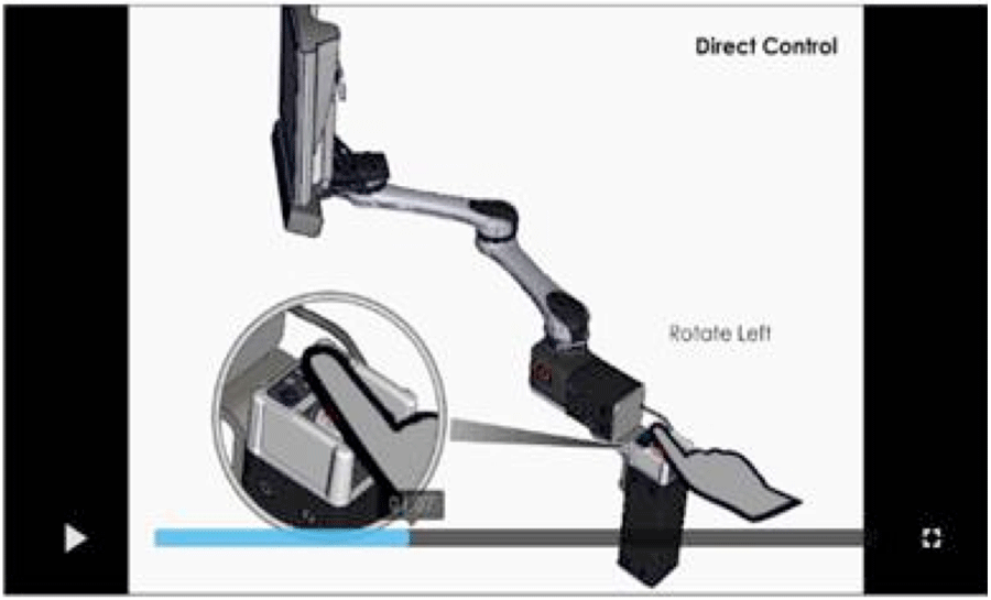
Video simulations were developed using SolidWorks models in Composer, a related software program. Models are imported and animated according to a storyboard, demonstrating how switches and the End Cap keypad could be used to operate a Single Joint; and how switches and the Control Pad could be used to operate a Multi-joint system. Individuals with disabilities and professionals viewed the videos online on a private site. Online questionnaires were completed to provide feedback and suggest changes.
Multi-Joint Display Development
Display choice:
The original display concept was a simple PCB with LEDs which lit up in a scanning array. As various system configurations were considered (ie Dual, Single, height and tilt) and the limitations were clear, it was obvious that an interactive graphic display was the better option.
Wireframe:
A wireframe diagram was developed to fully understand the user interface architecture and guide the design and software development process.
User Profiles:
User profiles were developed, based on access methods.
- Touch screen, direct
- Touch screen, limited range (ie, MD)
- Single switch, timed scan
- Single switch, step scan
- Two switch, step-select
Storyboard for each User:
Storyboards depicting the action taken and results were developed for each user, performing each of the three main functions: selecting and moving to a target spot; adjusting an individual joint; and changing levels.
Visual display and menu of options:
Many graphic representations for the display were developed. The goal is to clearly present choices to the end user, minimize switch hits to execute a task, ensure the actions and choices are consistent and available action options are logical and appropriate.
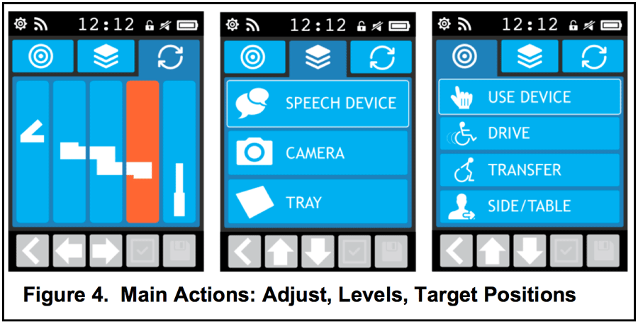
Visual display of 3 main actions:
- Adjust individual joints
- Select joint; then select direction
- Warning icon blinks when Joint is disengaged
- Levels—sets of target positions
- Up to 5 target positions per Level
- for different devices, settings or people
- indicated with icons and words
- Target positions (ie Use, Drive, Transfer)
- Indicated with icons and words
Settings:
Available settings include color schemes, scan speed, movement speed, auditory feedback, time, icons and words.
future work
Usability testing:
Hands-on usability testing will take place when working prototypes are available. The End Cap will first be tested, followed by the Control Pad. Up to 50 professionals and 25 end users will test the user interfaces.
Graphic display simulator:
Once User and Action scenarios are completed, screens and actions will be coded in the graphics microcontroller and test subjects can “use” the User Interface via a graphic display.
Settings:
User setting screens to be developed.
On-board video tutorials
are planned, and will be stored on the SD card.
Factory-set Target positions
Target positions will be pre-loaded with locations for common devices (ie a Drive, Use and Transfer position for an iPad, laptop and tray). Users will need to adjust them, but it is presumed this may be helpful and will simply require adjusting rather than starting from scratch.
Apps:
are to be developed which replicate what can be done on the Display. The apps will allow for access via phones, tablets and computers. There will be more customization, simulations and tutorials available via the apps. The site will have downloads for updates and remote troubleshooting capabilities.
conclusion
Considerable thought has been given to the potential end users and others who may use and control the power mount. Considering various Users and Use Scenarios is critical in developing a User interface that works well.
Various approaches and tools were used to develop and simulate how the device might work in order to solicit feedback. This up-front investment in time makes it easier to code and minimizes the programming time. Most importantly, it greatly improves the likelihood of developing an exceptionally intuitive and easy-to-use interface.- Website: Jaco Arm User Guide. Retrieved December 5, 2010, from www.kinovarehab.com
- Website: iArm (MANUS) Retrieved December 5, 2010, from http://www.assistive-innovations.com/
- Goodwin, D. M., Lee, N.K. 2014. Design and Development Process: Accessible, Affordable and Modular Robotics. Proceedings of the RESNA 2014 Ann Conference, Indianapolis, IN.: RESNA Press.
- Portoghese, C., Goodwin, D. M. 2014. Development of Accessible Powered Mounting Technology. Proceedings of the 2014 International Seating Symposium, Vancouver, BC.
Acknowledgements
Research reported in this publication was supported by the Eunice Kennedy Shriver National Institute of Child Health & Human Development of the National Institutes of Health under Award Number R44HD072469.
The content is solely the responsibility of the authors and does not necessarily represent the official views of the National Institutes of Health.