Participatory Action Design of a robotic mobility device graphical user interface
Katy Riojas; Jorge Candiotti, BE; Brandon Daveler, MS; Garrett Grindle, MS; Hongwu Wang, PhD; Rory A. Cooper, PhD
Quality of Life Technology Center- Research Experiences for Undergraduates,
Department of Rehabilitation Science and Technology, Human Engineering Research Laboratories, The University of Pittsburgh, Pittsburgh, PA
Abstract
Electric powered wheelchair (EPW) user interfaces are crucial to the proper functioning of EPWs. The improvement of these interfaces has the potential to increase the independence and mobility of thousands of current and potential EPW users. As EPWs continue to advance, user interface design must follow suit to allow users to intuitively navigate through more complex sets of wheelchair functions. A wheelchair with incredible capabilities cannot improve a user’s quality of life if the user cannot operate it. This paper describes the participatory action design of a unique and intuitive user interface for the MEBotv2.0. The MEBotv2.0 is a novel robotic electric powered wheelchair that enables users to adapt to their environment and preferences by selecting from a series of driving applications. The first component of this participatory action design consisted of the design and fabrication of the physical housing of the interface. The second phase consisted of the design and implementation of a novel graphical user interface that allows the operator to easily communicate with the wheelchair. The third phase involved EPW users’ feedback toward the final prototype of the graphical user interface. This participatory action design demonstrates the potential for the advancement of EPW interfaces using a user-centered design approach.
Background
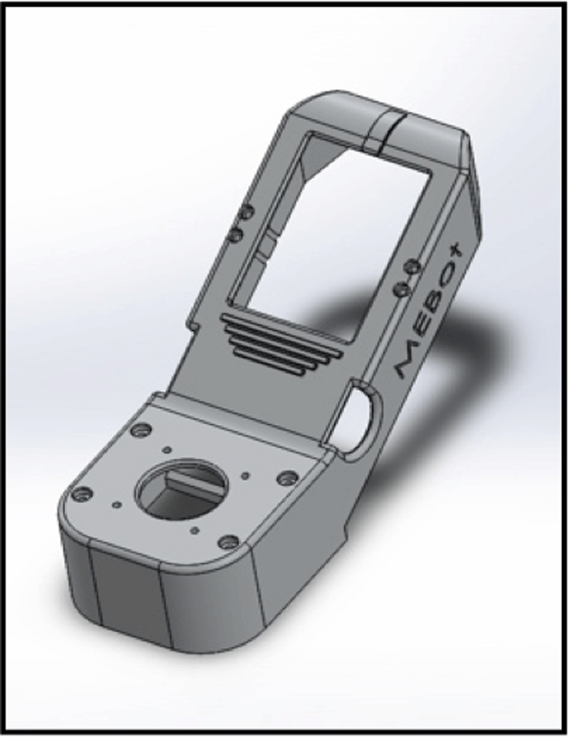
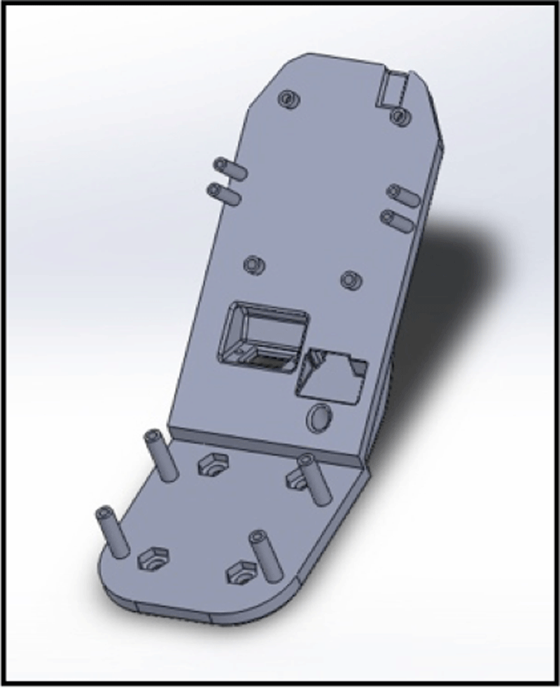 Figures 1 and 2: MEBotv2.0 User Interface Housing CAD Models
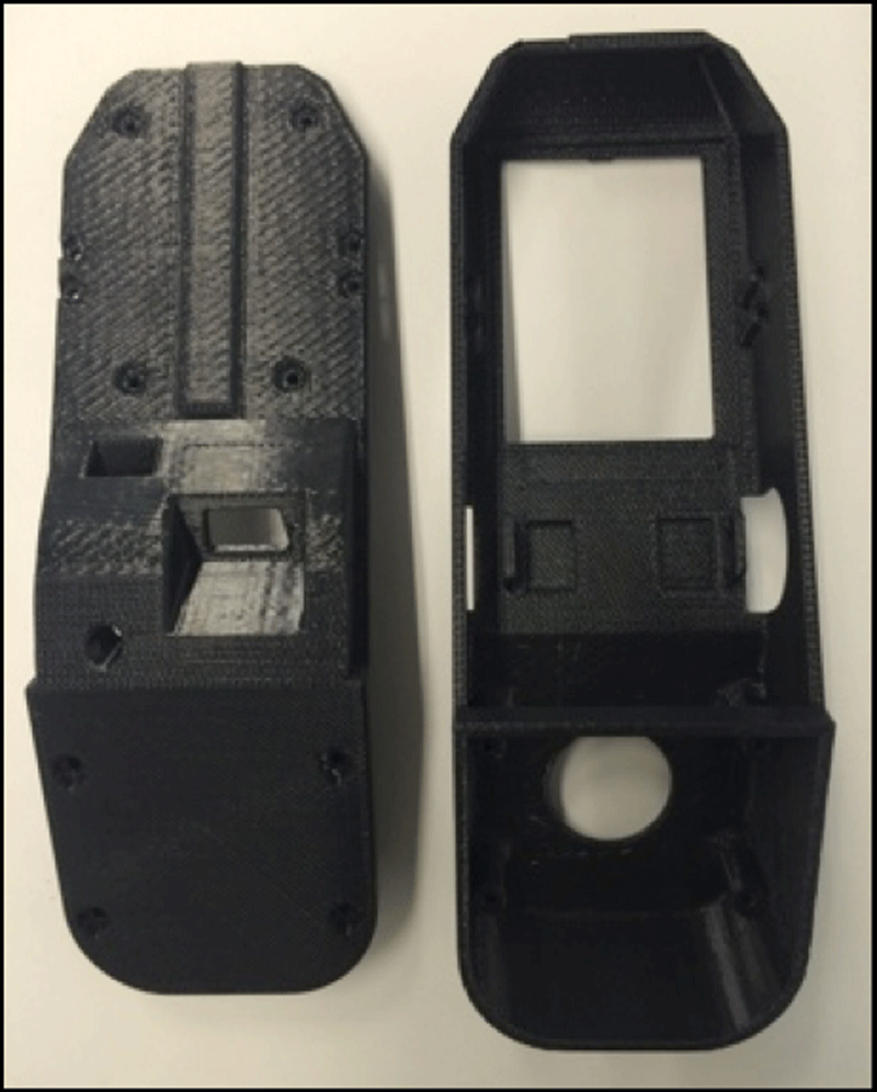
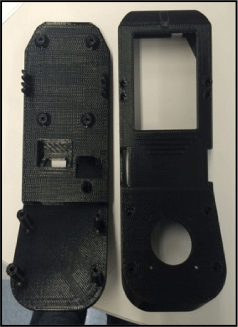 Figures 3 and 4: Fused Deposition Modeling 3D printed CAD models of Housing
 Electric Powered Wheelchairs (EPWs) are essential components of the lives of older adults and of many persons with disabilities. EPWs provide mobility for over 200,000 people every day (Wang, Salatin, Grindle, Ding, & Cooper, 2009). These wheelchair users consistently encounter dangerous obstacles such as rough terrain, curbs, and slippery surfaces (among others). As a result, potential injury due to wheelchair accidents is a significant issue for EPW users. In 2003 alone, the United States emergency departments reported over 100,000 wheelchair accidents (Xiang et al., 2003). Traditional wheelchairs do not give users optimal ability to avoid or overcome dangerous obstacles such as loss of traction, getting stuck, or loss of stability (Salatin, 2010). Recently, EPWs have improved to be able to adapt to the current environment and to the individual. One such novel EPW is the MEBotv2.0, the second version of a robotic electric powered wheelchair whose special functions include drive wheel position, self-leveling, traction control, balance mode, curb climbing, and indoor/outdoor mode (Wang, 2013). One of the most important features of an EPW is the user interface, which typically includes switches, a microcontroller, and a graphical user interface (GUI). A GUI is the displayed system of buttons, icons, and other objects that allows the user to select and access information through the computer in the wheelchair. GUIs are essential to the proper functioning of EPWs and user approval of the wheelchair in general. Current GUIs do not provide users with the ability to navigate through the complex driving applications of the MEBotv2.0. As a result, the development of a new and improved interface is necessary to allow users to effectively use the MEBotv2.0.
In a study by Fehr, Langbein, & Skaar (2000), 85% of clinicians reported seeing patients who cannot operate a powered wheelchair due to lack of motor skills, visual acuity, and/or strength (Fehr et al. 2000). Because rapid growth is predicted in the number of specialized EPW users in the coming years, the development and research of EPW user interfaces must keep pace (Cooper, R.A., Cooper R, & Boninger, 2008). If safer and more reliable technology is developed, it has been estimated that the number of EPW users would almost double (Cooper, et al., 2008).
Improvements to an EPW user interface should better integrate the capabilities of both the user and technology to provide more intuitive device control (Cowan et al., 2012). Considerations include size, placement, and type of hardware as well as color contrast and feedback mechanisms of software. The main goal of this unique user interface design is to maximize user functionality with technology assisting when necessary (Hoffman 2009).
PURPOSE
The purpose of this project using a user-centered design approach was to:
- Design and fabricate an accessible, user-friendly, durable, and aesthetically-pleasing user interface assembly for the MEBotv2.0
- Develop and implement a unique and innovative graphical user interface to allow a user to choose an advantageous driving mode and give clear visual feedback
Methodology
Design Criteria
The first step of the participatory action design to create the MEBotv2.0 user interface was to develop a set of design criteria. Criteria was based on current commercial EPW interfaces, the unique features of the MEBotv2.0, and input from the research group consisting of clinicians, engineers and experienced wheelchair users (Wakefield, 2006; “C500 Corpus 3G”, 2014; “Quantum”, 2014). A list of design criteria was set based on hardware and software requirements (Table 1, Table 2).
| LCD Screen | 3” x 2.5” angled at 30 degrees to improve visibility |
| All Components | Compatible with selected BeagleBone Black microcontroller (BeagleBone.org, Richardson, TX). |
| Switch Alignment | Aesthetically pleasing arrangement (aligned horizontally) |
| Power Switch | Maximum durability |
| Potentiometer | Regulates speeds [0≤speed≤6] mph |
| *Bolded items are criterion specifically necessary for the MEBotv2.0 | |
| Programming Language | Ability to bridge high and low level programming concepts and support real-time, high performance applications |
| Windowing System | Ability to compile C++ code |
| Method of Design | Design GUI based on user feedback for more intuitive operation |
| GUI Button Design | Large, vertically aligned GUI Buttons for simple toggle and selection |
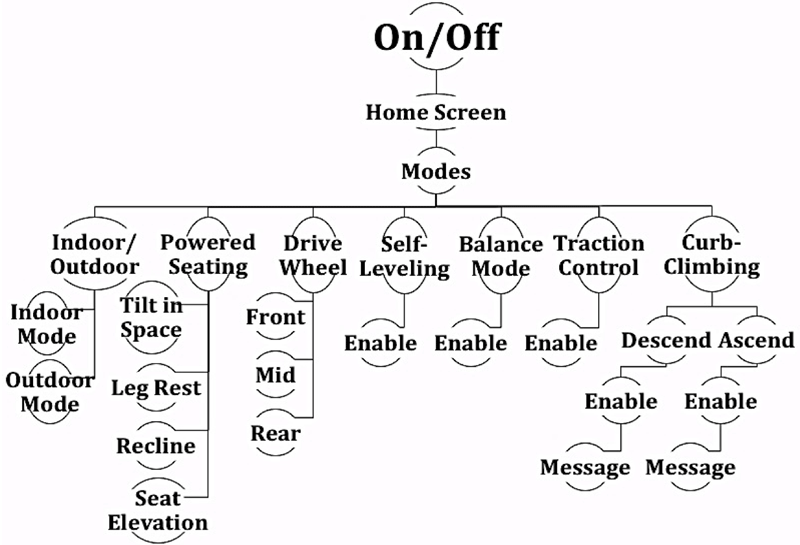 Figure 5: GUI Hierarchy Tree
 Next, the average dimensions of current commercial user interfaces were measured (Table 3), and design criteria for the size of the housing were set for the MEBotv2.0 wheelchair user interface (Table 4).
|
Model |
||
[Length in Inches] |
Invacare (CMPG+) |
Quantum (Q-Logic2) |
C500 Permobil |
Height |
1.5"-2.5" |
1-1.5 |
1-1.75 |
Width |
2.5-3 |
3 |
2.75 |
Top Half Length |
3 |
4.5 |
5 |
Bottom Half Length |
3 |
3.25 |
3 |
Screen Angle |
~15° |
~30° |
~30° |
Joystick to Switch Distance |
1.5 |
1.25 |
1.8 |
Height |
1"-2.5" |
Width |
2.5"-3.2" |
Top Half Length |
3"-6.0" |
Bottom Half Length |
3"-3.3" |
Screen Angle |
30 |
Joystick to Switch Distance |
1"-1.5" |
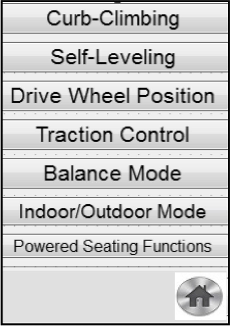
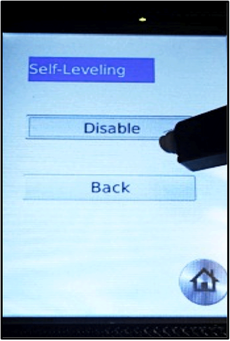 Figures 6 and 7: Mode Select screen of GUI (left) and Self-Leveling Screen of GUI (right)
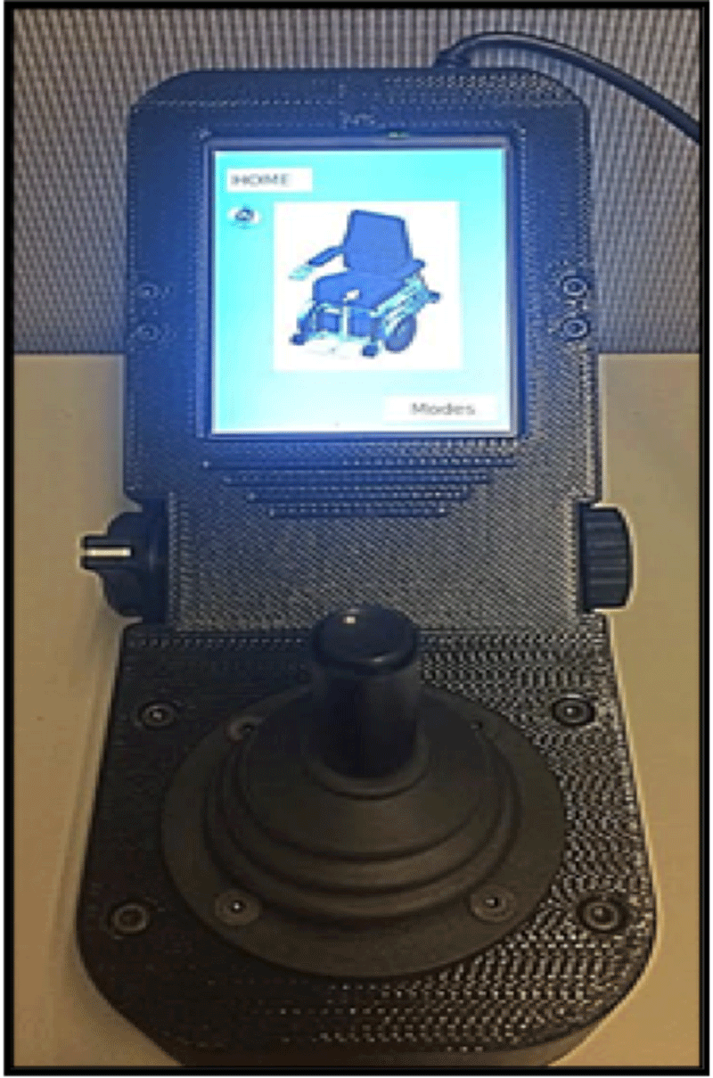
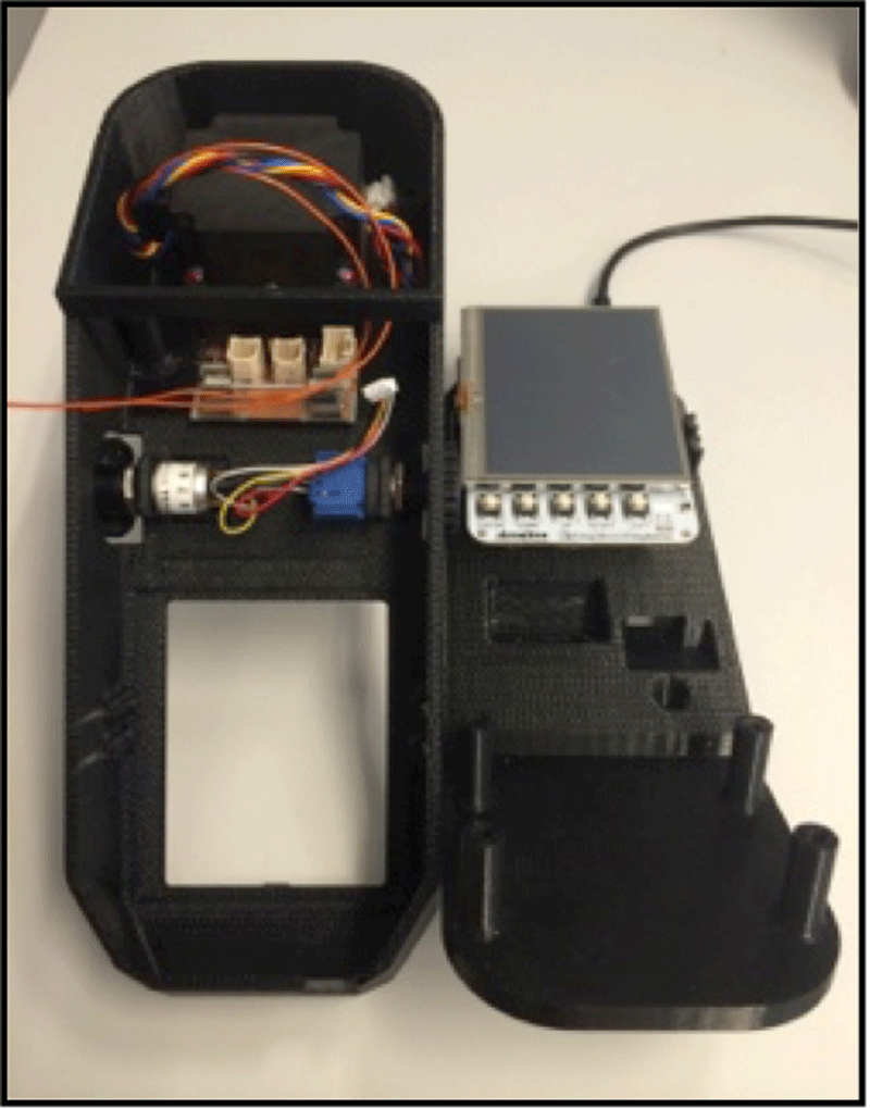 Figures 8 and 9: Assembled MEBotv2.0 User Interface with Home Screen (left) and inside of assembly (right)
 The next step of engaging in the participatory action design was to create a CAD model of the housing and bottom plate (Figures 1 and 2). Considerations in housing design included packaging and fixturing requirements for the user interface components (such as the potentiometer and microcontroller), placement of components, and complying with the specified size criteria. The housing and bottom plate were then printed using Fused Deposition Modeling (FDM) 3D printing.
The third step of creating the MEBotv2.0 user interface was to design and implement a GUI to appear on the LCD screen attached to the BeagleBone Black microcontroller (CircuitCo, Richardson, TX). The housing, switches and joystick, microcontroller, LCD screen, and all other components of the MEBotv2.0 user interface were then attached and tested. User feedback was gained from a focus group of 12 EPW operators regarding the accessibility and intuitiveness of the assembled wheelchair user interface. EPW operators were 18 years or older, used an EPW as their primary means of mobility, and actively used their EPW outside of the home at least three times a week. The users were shown a video of the GUI navigation and their suggestions for improvements were documented. Subjects for this study were recruited by the University of Pittsburgh with IRB approval.
Results
The resulting 3D printed CAD models, as shown in Figures 3 and 4, successfully housed all of the required components and featured mechanisms for associated components as well. Required components were kept to a minimum to ensure simplicity in operation.
The inside of the housing assembly as shown in Figure 9 consisted of a joystick, an interface circuit board, a BeagleBone Black microcontroller, an LCD cape, a potentiometer, and a mode select switch. The housing had a maximum height of 2.1”, a width of 3.25”, a perpendicular length of 8.45”, and a screen angle of 30 degrees, meeting the specified size criteria.
The graphical user interface (GUI) was designed using Desktop Qt Creator (Qt Digia, Santa Clara, California) and deployed to the BeagleBone Black microcontroller. The interface was displayed on the LCD3 cape attached to the BeagleBone Black. Users interacted with the interface using the joystick, the mode select switch, and the joystick select button. The interface consisted of 11 different forms that allow users to select their preferred driving mode and individualize the wheelchair driving mode and position to match their preferences. Each screen contained large type and sharp color contrast for maximum visibility.
The GUI Hierarchy, as shown below in Figure 5, displays a unique system by which users can negotiate the variety MEBotv2.0 applications. In addition to the items listed, “back” and “home” buttons were included on each screen. User feedback indicated that users believed the GUI would improve user mobility options. Figures 6 and 7 show the mode select and self-leveling screen of the GUI. Finally, Figure 8 shows the final assembled user interface with the home screen of the GUI open.
A more complete summary of specific feedback comments is shown in Table 5. The trend of user feedback suggests limiting the number of screens contained within the GUI because of the slightly extensive menu that may require a learning curve. Another suggestion was to add a customization screen to set default preferences. Finally, users suggested setting certain modes, like traction control, as automatic features.
| Suggestions for Interface | General Comments |
| Single Modes screen | The application definitely improves user access |
| Customization Screen | |
| Self-leveling, traction control, and indoor/outdoor mode: users should toggle joystick to quickly enable/disable | Touchscreen not a bad option for all users |
| Add icons in the Home Screen to show enabled applications | Curb Climbing application showed many steps |
| Automatically enable certain applications at all times (traction control) | Sun might affect screen visibility |
Discussion
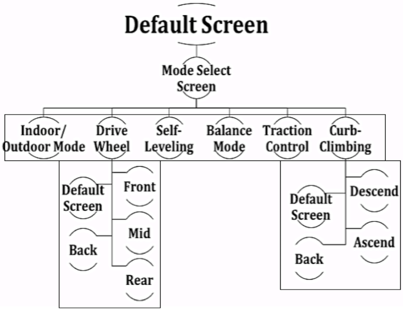 Figure 10: Potential Second Iteration GUI Hierarchy
* Rectangles represent one screen
The MEBotv2.0 user interface provided a large display screen and joystick to enable users with less visual acuity and less motor control to operate the robotic wheelchair. The switches responsible for controlling specific aspects of the graphical user interface were selected based on user feedback so as to ensure accessible, intuitive functioning of the MEBotv2.0.
The resulting MEBotv2.0 wheelchair user interface proved successful in that it:
- Consists of accessible, durable hardware with a minimum number of switches
- Incorporates a graphical user interface that allows intuitive, visible negotiation of a number of novel robotic wheelchair functions that could otherwise be fairly difficult to navigate.
Limitations and Future work
Future studies should include feedback from more than the twelve EPW users employed in this study. Future work may include a user interface whose size is determined exclusively by the designer and user feedback and not based on commercial interfaces. Finally, different unconventional features such as a waterproofing flange on the top of the housing should be considered. A potential simplified GUI hierarchy is proposed in Figure 10.
References
Brisson, L. J. (2001). Designing user interfaces for severely handicapped persons. In Proceedings of the 2001 EC/NSF workshop on Universal accessibility of ubiquitous computing: providing for the elderly.
C500 Corpus 3G (2014) - Permobil US Manuals & Documents. Permobil, Retrieved from: http://manualsdocs.com/pdf/c500-corpus-3g-permobil-us.html
Cooper, R. A., Cooper, R., & Boninger, M. L. (2008). Trends and issues in wheelchair technologies. Assistive Technology, 20(2), 61-72.
Cowan, R., et al. (2012). Recent trends in assistive technology for mobility. Journal of NeuroEngineering and Rehabilitation 2012 9:20.
Fehr, L., Langbein, W. E., & Skaar, S. B. (2000). Adequacy of power wheelchair control interfaces for persons with severe disabilities: A clinical survey. Journal of Rehabilitation Research and Development, 37(3), 353-360.
Hoffman, A. H. (2009, November). Design of robotic devices to assist persons with disabilities. In Technologies for Practical Robot Applications, 2009. TePRA 2009. IEEE International Conference on (pp. 1-4). IEEE.
Quantum, the Rehab Power Chair Solutions Company (2014). Quantum Rehab. Retrieved from: http://www.pridemobility.com/pdf/Brochures/Jazzy/quantum_brochure.pd
Salatin B. (2010). Electrical powered wheelchair driving outdoors: user needs evaluation and the development of an advanced controller. (Master thesis) Retrieved from ETD
Wakefield, II, T.D. (2006). Integral Joystick Display for a Power Driven Wheelchair. U.S. Patent No. 7,003,381. 21 Feb. 2006. Print.
Wang H, Candiotti J, Shino M, Chung CS, Grindle GG, Ding D, Cooper RA. (2013). Development of an advanced mobile base for personal mobility and manipulation appliance generation II robotic wheelchair, J Spinal Cord Med. 36(4): 333-46.
Wang, H., Salatin, B., Grindle, G. G., Ding, D., & Cooper, R. A. (2009). Real-time model based electrical powered wheelchair control. Medical engineering & physics, 31(10), 1244-1254.
Xiang, H., Chany, A. M., & Smith, G. A. (2006). Wheelchair related injuries treated in US emergency departments. Injury prevention, 12 (1), 8-11.
Acknowledgements
Funding for this research came from the National Science Foundation (NSF), Quality of Life Assistive Technology Center (QoLT REU Grant #1358903), and the Department of Veterans Affairs (VA Center Grant #B6789C). We thank the Human Engineering Research Laboratories for the use of their facilities and equipment. Approval of this project was obtained by Pitt IRB #14050452.
The contents of this paper do not necessarily represent the views of the Department of Veterans Affairs or United States Government.