D Goodwin, P Loeffler, M Stone
BlueSky Designs, Inc.
INTRODUCTION/ABSTRACT
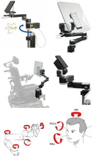
This paper describes robotic mounting solutions and user interfaces developed to satisfy a wide range of needs for different end users. Flexible user interfaces and control options expand access and improve usability. Different robotic configurations using one or more modular power joints allow flexibility in scaling the solution to address diverse end users and use cases. User and clinician input were critical in influencing the design and reshaping the solution.
Wheelchair-mounted robotic arms are not new, but most wheelchair-mounted robotic arms have focused on grasping and manipulating objects and have limited load capacities, up to 3.3 pounds (1.5 kg) at medium reach. [1,2] Advancements in technology, materials and manufacturing methods offer opportunities to create improved robotic systems and more accessible user interfaces. The new robotic mounting solutions in this paper provide people with the ability to safely and easily move and reposition things attached to their wheelchair or bed.
The outcomes are easy-to-use robotic solutions with flexible interfaces that range from very simple to very deep. A person can move individual joints independently and move to user-specific custom target positions for different devices. [3] The flexibility and intuitiveness of the user interface has been tested and ease of use has been proven. The different inputs and robotic configurations provide increased independence in various applications, for a wide range of end users, using familiar accessible controls and switch access modes.
RELATED RESEARCH AND PREVIOUS STUDIES
Historically, studies of wheelchair-mounted robotic arms such as the Manus have been rife with examples of researchers trying to make the user interface user-friendly. [4,5] Recent research has focused on comparing the speed with which an end user is able to complete a task using different robotic arms. [2] In most cases, the robots and tasks focus on robotic arms intent on grasping and manipulation.
Both single user studies and research and development projects have shown a demonstrated interest and use for motorized arms with a single joint involved, such as a backpack-retrievers, and communication device or chin joystick positioners. [6] However, none have been commercialized.
The robotic arm described in this paper focuses on easily and independently moving devices with loads up to 15 pounds (6.8 kg) into a “use” position or to several other preferred positions. A person can store target positions for up to five devices. In addition, they can adjust individual joints within the system.
METHODS/DESIGN DEVELOPMENT
Soliciting input and feedback from stakeholders
Input into the needs and preferences for access and the technical specifications for the robotic mount were solicited from end users, their family members and clinicians. Feedback on working prototypes or mock-ups of the user interface was sought from these stakeholders at conferences, online, or in clinical and home settings. Methods included online questionnaires via list-servs, focus groups with ATPs and staff at rehab centers and organizations, face-to-face interactions at conferences and one on one meetings with individuals and family members. Feedback was gathered via prepared surveys, or verbally with key questions being asked as the team prepared to make design decisions. Hands-on testing and use by end users, clinicians and staff unfamiliar with the device and interface was critical and very informative. Observations as a person tried to control the system provided very important feedback, showing where people got confused, how or whether they could recover, and how easy or difficult they found it to operate. Test subjects were encouraged to verbalize their thoughts, assumptions and questions during testing. User tests included some trials with instructions, and some without. [7]
Accessible robotic arm development

Various configurations resulted
Hybrid systems combine a single power joint with a movable mounting arm, which offers flexible positioning. A person can have a powered shoulder, or powered tilt. This allows a person to use a switch to move their mount out of the way for transfers, or to pull up to a table or sink. The power tilt allows repositioning to see where one is driving or to see their teacher or a movie.
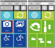
Multi-joint power mounts allow a person to move devices to up to six memorized target positions, or to adjust individual joints. The multi-joint system is controlled via an app, accessed by one or two switches.
Future directions: Auto-positioning technology
People who are essentially quadriplegic, with significant mobility impairments and limited to no upper extremity use are dependent on others to position and access devices such as eye gaze speech devices, call systems, phones, tablets, wheelchair controls, and hydration and suctioning tubes. The auto-positioning power mount responds to a person’s position, automatically moving things to known usable positions. [10]
Auto-positioning technology uses computer vision to detect specific targets, such as facial features to control the robotic mounting and positioning system. The mount repositions devices for best access without assistance, even if their position changes. This results in increased independence and reduced reliance on others. It could enable continuous access to eye gaze communication; maintain one’s ability to drive a wheelchair by auto-positioning head array or joystick controls; or allow a person to drink or suction themselves, for hydration and respiratory health. As a result, a person and their family can experience health and psychosocial benefits. [11]
USER INTERFACE/ACCESS OPTIONS

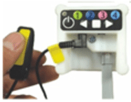
System controls are accessed via accessible switches, a built-in keypad or directly touching the app, when applicable. Each system includes a Power Pack with an End Cap with built-in switch jacks, a power supply jack and the cable which connects to the power mount to supply power and data.
Keypad control: The End Cap keypad includes a Power button, an LED indicator for feedback, 4 numeric keys to allow setting programmed positions, right and left arrow keys, and a Stop key to stop movement. These are meant for attendant control, so that they needn’t user a user’s switches. The keypad is also used for custom settings, such as the back-off force setting (Stop key plus a number key) and the side of the wheelchair the mount is attached (Stop key plus an arrow key). This determines the direction the mount moves to go to its home/away position, so it does not try to move through the person.
Switch control: Switches act differently based on which jack it is plugged into, and which configuration is used.
Hybrid system/Left jack: Switch is depressed and held to move the mount. When released, it stops. Next switch hit, it moves the other direction.
Hybrid system/Right jack: Switch is tapped and released. It moves to one of the two preset positions. The next switch hit, it moves to the second preset. If the switch is hit as it is moving, it stops.
Hybrid system/Two switches: Each switch is for a specific direction. Press and hold to move. Release to stop.

Direct touch: Individuals who can access the screen on the paired device can use the app directly via touch.
Single Switch, Step/Select: Pressing a switch in Left jack advances the highlighted selectable button on the screen. Press and hold until the entire button is orange selects that button. In the case of Target position, it goes to the selected programmed position; in the case of Adjust screen, an additional press and hold moves the selected joint in one direction. With a subsequent press and hold, it moves the other direction.
Two Switch, Step/Select: Operates similar to above, but Left switch is for stepping to next option; Right selects it.
Single Switch, Timed scan: Pressing and releasing a switch in the Right jack starts an automatic scan. The scan speed is adjustable in the app settings. Press and release to stop the scan and activate the highlighted button. Then, press and hold to Adjust; or press and release to go to the target position.
Targets and Groups: The switch-accessible app allows customization for the individual’s set up, including the ability to set up to six Target Positions per Group of targets. Groups of Targets may be set for specific devices or environments (ie, bed, wheelchair or workstation). Up to five different Groups may be established. This allows a person to quickly move their mounted device to the most commonly used positions. They can program as many or few Target positions as they want.
Adjust Individual Joints: Joints can be adjusted individually from the Adjust screen.
App settings: A person can use different modes of control, as described above. They can also choose different screen display and/or access settings, such as scan speed, auditory feedback on scanning, options for a high contrast or color screen. They can choose icons and names for the Target positions and devices. Settings also include whether different screens are displayed and/or accessible via touch only, or via switches. This allows the app to be simplified, and prevents access to actions determined to be unnecessary, confusing or unsafe for the end user. For example, the person setting it up may only want the end user to be able to cycle through Target positions, in which case the Adjust and Group tabs would not be switch-accessible, or it may not be displayed at all.
RESULTS

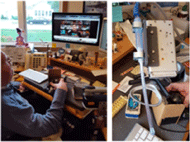
L: Workstation R: Suction tube attachment
It was found that individuals were very satisfied with the controls, finding them intuitive and easy to use. They were very satisfied with their ability to move mounted devices themselves. Changes were made at various stages of development in response to feedback from those testing it. For example, with the Auto-positioning system it was found that once it found the person and was in a usable position, it should stop tracking their every move. In testing the Auto-positioning system, both individuals with disabilities and caregivers felt it was Very Important a person was able to position things themselves. “I don’t need to worry about him, so I can do things I need to get done, like do the dishes, vacuum or go grocery shopping.”
USE CASES
Suctioning using a Hybrid shoulder mount
Scott is a young man with Spinal Muscular Atrophy. He cannot swallow independently and was unable to suction himself. He lives in his own apartment, with Personal Care Attendants there for the most part. However, there are 5-hour windows of time in which he does not have anyone with him. This causes him anxiety, in that he feels he could “drown in my own saliva”. He had been going to the ER frequently to address respiratory issues and told his home health care nurse that he felt he would be healthier if he could somehow move his suction tube to suction himself.
Scott has very limited range of motion, with just the ability to use his fingers if his hand is positioned for him. His OTs worked with him and determined he can use his thumb for one switch, to move the mount, and his little finger for the other, to turn on the suction. He uses a Hybrid system with a power shoulder joint to bring his suction tube to his mouth, and to send it back to an away position. After trying both the single switch with momentary action and the option to go between two target positions, he chose the former. That way, he felt more in control of the movement. Since having this ability, he has been healthier and has been able to interact with other computer gamers, because he can talk while playing. It has also had a significant positive psychological impact. [12]
Moving a device for driving
Two students, one nine years old and one eighteen, who use eye gaze speech devices attached to their power wheelchairs use Hybrid systems, one a power tilt and one a power shoulder. In each case, they have a “Use” and “Drive” position so they can better see when driving, yet quickly move it back to communicate. They also move it for other purposes, for example, to better see their teacher or others and to see their computer or television.
DISCUSSION/CONCLUSIONS
The described robotic arms and user interfaces have been shown to be easy to use and adaptable to various individuals for different purposes. Involving clinicians, end users and family members had a significant effect on the usability and resulting design configurations. Future involvement of and communication with those using the systems will serve as ongoing “field testing and research” and influence the evolution of the designs.
REFERENCES
- Regalbuto, MA, Krouskop, TA, Cheatham, JB. 1992. Toward a practical mobile robotic aid system for people with severe physical disabilities Journal of Rehabilitation Research and Development, Vol. 29.
- Chung, CS, Wang, H, Cooper, RA. 2013. Functional assessment and performance evaluation for assistive robotic manipulators: Literature review. Journal of Spinal Cord Medicine, July 2013.
- Goodwin, D, Lee, N, Stone, M, Kanitz, D, 2015. Accessible User Interface Development: Process and Considerations. RESNA 2015 Annual Conference.
- Tijsma, HA, Liefhebber, F, 2005. Evaluation of new user interface features for the MANUS robot arm, January 2005.
- Tsui, KM, Yanco, HA, Kontak, D, Beliveau, L, 2008. Development and evaluation of a flexible interface for a wheelchair mounted robotic arm, Proceedings of the 3rd ACM/IEEE International Conference on Human Robot Interaction.
- Daid, M, Devadas, N, Moutal, E, Thawani, T, You, J, 2014. Backpack Retriever, RESNA Student Design Competition.
- Sundberg, E., Goodwin, D. M. 2007. Usability Testing of Repositionable and Customizable Locking Mounts with Rehabilitation Professionals. Proc RESNA 2007 Ann Conf, Washington, DC: RESNA Press.
- Goodwin, D. M., Lee, N.K. 2014. Design and Development Process: Accessible, Affordable and Modular Robotics. Proceedings of the RESNA 2014 Ann Conference, Indianapolis, IN.: RESNA Press.
- Portoghese, C., Goodwin, D. M. 2014. Development of Accessible Powered Mounting Technology. Proceedings of the 2014 International Seating Symposium, Vancouver, BC.
- Goodwin, D., Loeffler, P., Stone, M., 2017. Automatic Positioning of Communication Devices, RESNA Late-Breaking Poster Session; 2017.
- Goodwin, D., Gitlow, L., Kinney, A., Chapman, S., 2014. Functional and Psychosocial Impact of Accessible Mounting, Proceedings of the 2014 International Seating Symposium, Vancouver, BC
- Vos-Draper, T., Kane, M., Goodwin, D., 2016. Power Mounts: Create Powerful Solutions for Your Clients, RESNA Workshop; 2016.
ACKNOWLEDGEMENTS:
Funding provided by NIH/NICHD SBIR grants (1R44HD093467-01, 5R44HD072469-03, 2R44HD072469-02, 1R43HD072469-01); NIDILRR SBIR Grant H133S060096; and the RERC on Wireless Technology LiveWell program (NIDILRR Grant 90RE5023).