Kieran J. Eveleigh1, Marc Doumit1
1University of Ottawa, Mechanical Engineering Department
INTRODUCTION

KAFO knee joints can provide uninhibited motion in the sagittal plane, can be fully locked, or can feature controllable locking mechanisms. Since many KAFOs feature permanently locked knee joints, they prevent the user from flexing their knees during swing. To compensate for the stiff-knee gait, locked-knee KAFO users must circumduct their braced leg in order for their foot to clear the floor during swing. When using locked-knee and unlocked-knee KAFOs on flat surfaces, gait efficiencies have been found to be only 58% and 62% of that of normal gait, respectively [4]. The combination of increased energy expenditure, joint and muscle pain as well as a decrease in gait efficiency explain why locked-knee KAFO rejection rates range from 60-100% [3]. While some users require their knee joint to be locked throughout gait to preserve stability, a certain group of users benefit from a device that prevents knee flexion at critical intervals during gait, specifically when the affected limb is weight bearing. This specific type of KAFO is known as a stance-control knee-ankle-foot orthosis (SCKAFO).

The design of the FreeWalk and UTX Swing also features a switch for manual disengagement of the knee joint which is useful when the user wishes to perform actions such as sitting [5]. That being said, it is disadvantageous as the knee joint only locks when the user fully extends their leg. If an individual stumbles or falls short of full knee extension during swing phase, the knee mechanism would not lock, providing no assistance and risking the stability of the user. Additionally, for users who wish to walk on slopes or stairs, the knee mechanism may not activate at the appropriate time (or may not activate at all) due to excessive or lack of dorsiflexion.
SCKAFO MODELING AND DESIGN

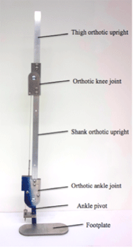
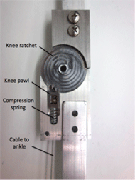
The knee joint (Figure 2) includes a pawl held in place by a compression spring and three ratchet teeth. When the user dorsiflexes, a control cable connecting the ankle joint to the knee joint pawl translates inferiorly, temporarily compressing the spring. As the user plantar flexes, tension is relieved from the cable and the compression spring returns the pawl to its original position. The spacing between the ratchet teeth allows the knee joint to lock at full extension as well as at flexion angles of 10 and 20 degrees. While the spacing between teeth is slightly larger than the spacing between teeth in other SCKAFOs [6], the reduction in number of teeth reduces the number of instances where the ratchet teeth engage with the pawl and thus prevents undesired noise.
In order to accommodate users who achieve different maximum dorsiflexion angles, an adjustment mechanism for the disengagement angle was designed. The disengagement angle refers to the minimum angle of dorsiflexion required to fully disengage the pawl from the ratchet teeth in the orthotic knee joint. While the adjustment of the disengagement angle in many SCKAFOs occurs at the knee joint, it is done so at the expense of having bulky anterior knee joint protrusions. The adjustment mechanism in this SCKAFO is fully encased and located inferior to the knee joint in a less intrusive location (the ankle joint).
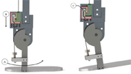
The ankle joint was first designed to accommodate a maximum disengagement angle of 15 degrees. As the user dorsiflexes, the cable bends around the contour of the ankle pivot which pulls the cable inferiorly from the knee joint. The disengagement angle adjustment mechanism features a cable passing through a thumb screw tapped in a metal plate, as well as a delay mechanism. The delay mechanism features two blocks referred to as delay block 1 (DB1) and delay block 2 (DB2) (Figure 3). With this design, two cables replace the function that is usually served by a single cable that pairs the motion of the ankle to the actuation of the orthotic knee joint lock. The inferiorly-located cable is referred to as cable 1 and the superiorly-located cable is referred to as cable 2.
On its superior end, cable 1 is anchored to DB1 (accented in red Figure 3). Inferiorly, it passes through the thumb screw to its anchor site. Cable 2 is anchored inferiorly to DB2 (accented in green in Figure 3) by means of a wire rope compression stud end fitting (not shown) and is anchored superiorly to the pawl in the knee joint. As the user dorsiflexes (Figure 3 A), cable 1 bends around the ankle joint pivot and DB1 is pulled inferiorly (Figure 3 B) until it comes into contact with DB2. As the user continues to dorsiflex, both blocks are pulled inferiorly (Figure 3 C). By the time the user reaches their maximum level of dorsiflexion, DB2 (and cable 2) will have translated inferiorly by a distance large enough to result in the disengagement of the pawl from the ratchet in the knee joint. During swing, compression springs located inferior to DB1 return it to its original position to prepare for the subsequent heel strike. Adjustments to the disengagement angle are made by turning the thumb screw which results only in the inferior translation of DB1, thus leaving the position of the pawl with respect to the ratchet in the knee joint unaffected. Kinematic modeling validation of the proposed design demonstrated that a single rotation of the thumb screw in the threaded metal plate would result in a 2 degree change in the disengagement angle.
SCKAFO MECHANICAL TESTING
Mechanical testing of the SCKAFO was performed using a motion capture system (NaturalPoint Inc., Corvallis, USA) and data was processed using MATLAB (Natick, USA). Three testing procedures were used to validate the design proposed in this study, each of which involved measuring the angles of the orthotic knee and ankle joints. The first testing procedure TP1 was used to determine if the motion of the orthotic ankle joint could actuate the lock in the orthotic knee joint in a consistent manner within a controlled setting. The second testing procedure TP2 was used to determine if the orthotic knee joint lock could be actuated in varying orientations. The third testing procedure TP3 assessed the device’s ability to accurately change the angle of ankle dorsiflexion that would result in the disengagement of the orthotic knee joint lock.

Eighteen trials were performed in TP1 according to this procedure. In TP2, the brace was removed from the mount and held with one hand on the shank upright and one on the ankle pivot. Similar to TP1, the ankle joint was moved into a more dorsiflexed position until the knee joint would unlock and the thigh orthotic upright would swing downward. A total of twelve trials were performed in TP2. The procedure from TP1 was followed in TP3, however for approximately every 15 trials, the adjustment mechanism was used to decrease the expected disengagement angle by 2 degrees (turning the thumb screw by 360 degrees). The adjustment process in TP3 was repeated 4 times, followed by a final half-turn of the thumb screw.
RESULTS

DISCUSSION
The results from TP1 fell short of the original objective of achieving a disengagement angle of 15 degrees, showing an average disengagement angle of 10.96 degrees. The discrepancy between the expected and actual result can be attributed to several factors, the most likely of them being the pre-tightening of one or both cables connecting the orthotic ankle and knee joints. Additionally, the ankle angle, defined as the angle between the shank and the ankle pivot (see Figure 1) was measured in the sagittal plane, defined by one of the motion capture system’s planes. If the SCKAFOs motion was not perfectly aligned with one of the motion capture system’s planes, observed joint angles may have deviated from actual joint angles.
In TP1 and TP3, the horizontal orientation of the SCKAFO ensured that the weight of the thigh upright would create a flexion moment about the knee joint that would help it flex when unlocked. In TP2, however, the SCKAFO was not oriented horizontally nor was it completely stationary. This changing orientation resulted in different forces being applied to the device at different non-horizontal angles (thus reducing the knee flexion moment arm) which may have impeded the unlocking of the knee joint.
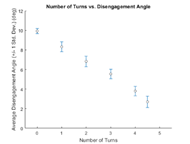
The primary goal of TP3 was to validate the ankle adjustment mechanism. It was hypothesized that a single turn of the thumb screw would result in a 2 degree change of the disengagement angle. The results from approximately 15 trials performed in each thumb screw position (0, 1, 2, 3, 4, and 4.5 turns) showed that a single turn of the thumb screw changed the disengagement angle by an average of 1.68 degrees. The discrepancies between the expected changes in disengagement angles and actual changes could be explained by potential differences between the actual component dimensions and the expected component dimensions. The ankle adjustment mechanism proved successful as it was able to consistently change the disengagement angle by a relatively constant value (1.68 degrees) for every full turn of the thumb screw. Note that in real life applications, extremely precise adjustments of the disengagement angle are not required before an individual first uses the device. The purposes of this adjustment mechanism are to help obtain a rough estimate of the disengagement angle before the user wears the device and then, once on, to offer the user an easy way to adjust this angle by small increments.
CONCLUSIONS AND FUTURE WORK
The stance-phase knee-ankle-foot orthosis (SCKAFO) introduced in this paper proves promising as it has the ability to prevent stance phase knee flexion and allow for uninhibited knee flexion during swing. Using three ratchet teeth spaced 10 degrees apart, the device can accommodate users who achieve full knee extension as well as those who fall short of full knee extension during an average stride. The proposed SCKAFO can accommodate maximum user ankle dorsiflexion angles within the range of 2.72 to 10.96 degrees, where the average reported maximum dorsiflexion angle during gait is approximately 8 degrees [7]. The device’s precision in changing from a locked to unlocked mode when mounted horizontally was demonstrated for a dorsiflexion angle of 10.96 degrees, with a single standard deviation being 0.43 degrees. Results were less precise when the device was used in a changing environment (handheld), with a larger sample standard deviation of 1.72 degrees when the mean dorsiflexion angle was 9.34 degrees. Finally, the device’s adjustment mechanism proved successful as it was able to accurately change the disengagement angle to within an average of 0.46 degrees of a desired value. Moreover, it shows potential to quickly make adjustments so that the SCKAFOs functionality can accommodate the needs of the user. Future work should include a more appropriate material selection for the SCKAFO to reduce wear between mating components. Additionally, reductions of the size of the ankle joint should be considered. Finally, several changes with respect to the knee pawl and ratchet should be considered, including the manner in which the pawl retracts from the ratchet (it should retract radially), rounding the pawl and ratchet teeth to reduce stress concentrations, decreasing the angle of the ratchet teeth to facilitate ratcheting and, finally, a mechanism should be included to allow for the manual unlocking of the knee joint so users wearing the SCKAFO can sit.
REFERENCES
[1] Herbert-Copley A. Design and evaluation of a variable resistance orthotic knee joint [thesis]. 2015.
[2] Kary JM. Diagnosis and management of quadriceps strains and contusions. Current Reviews in Musculoskeletal Medicine. 2010;3(1-4):26–31.
[3] Yakimovich T, Lemaire ED, Kofman J. Engineering design review of stance-control knee-ankle-foot orthoses. Journal of Rehabilitation Research and Development. 2009;46:257–68.
[4] Kaufman KR, Irby SE, Mathewson JW, Wirta RW, Sutherland DH. Energy-Efficient Knee-Ankle-Foot Orthosis: A Case Study. JPO Journal of Prosthetics and Orthotics. 1996;8(3):79–85.
[5] Otto Bock. Free Walk: Secure stance phase – lightweight and discreet. Germany: Otto Bock HealthCare GmbH; 2014.
[6] Naft JM, Newman WS, inventors. Becker Orthopedic Appliance Co Inc, assignee. Orthosis knee joint. US6770045B2. 2004-08-03.
[7] Whittle MW. Gait analysis: an introduction. 4th ed. Edinburgh: Butterworth-Heinemann; 2008.