N. Will![]() 1
1![]() , M. Sanchez
, M. Sanchez![]() 1
1![]() , B. S. Duerstock
, B. S. Duerstock![]() 1,2
1,2![]()
![]() 1
1![]() Weldon School of Biomedical Engineering, Purdue University,
Weldon School of Biomedical Engineering, Purdue University, ![]() 2
2![]() School of Industrial Engineering, Purdue University
School of Industrial Engineering, Purdue University
INTRODUCTION
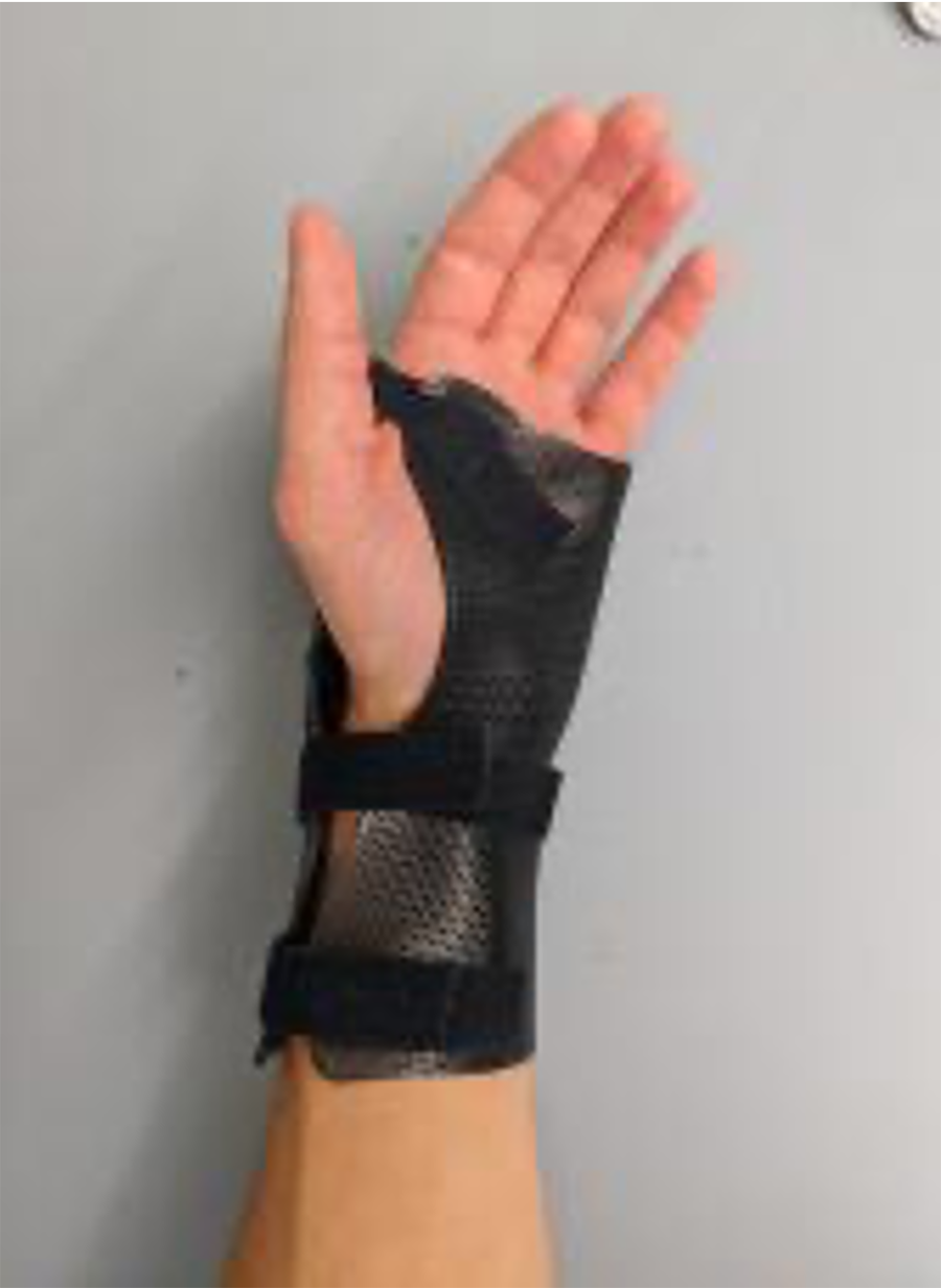
Every year, there are approximately 17,000 new cases of Spinal Cord Injuries (SCI) in the United States alone. 53.9% of SCIs occur in the cervical spine (C1-C7) and about 40-50% of these individuals have injuries in the upper and middle cervical region (C1-C5) that would require wearing wrist braces to keep wrists immobilized [1]. Individuals needing wrist braces usually have difficulties performing manual activities of daily life (ADL) such as writing or opening doors with keys, due to weakness or paralysis in the wrist flexor muscles [2]. Even though wrist orthoses primarily provide only support, with the addition of pockets in the palm, dining utensils, pencils, pens, or toothbrushes can be inserted to enable tetraplegics to perform certain ADLs independently. In previous studies, we explored the use of electromyography (EMG) and an inertial measurement unit (IMU) to develop a 3D printed multi-functional wrist orthotic (MFWO) which would allow users to control different actuators using a set of gestures [3]. The use of the IMU combined with an activation system allowed for a high accuracy in gesture detection. The implementation of a machine learning algorithm also allowed for an improved accuracy as well as a universal gesture recognition system [4-5]. The goal of the WristSense project is to create a wrist orthotic that is easily accessible and customizable, the 3D printed brace should be able to be created by a lay-user with minimal experience and using inexpensive, commercially available components. Figure 1 shows the 3D printed wrist brace that can, after printing, be heated and formed to the individual's wrist. Velcro straps secure the wrist brace. For this paper, we performed mechanical testing on different prototypes of the wrist brace to determine the optimal structure for wrist support, while also having minimal weight.
METHODS
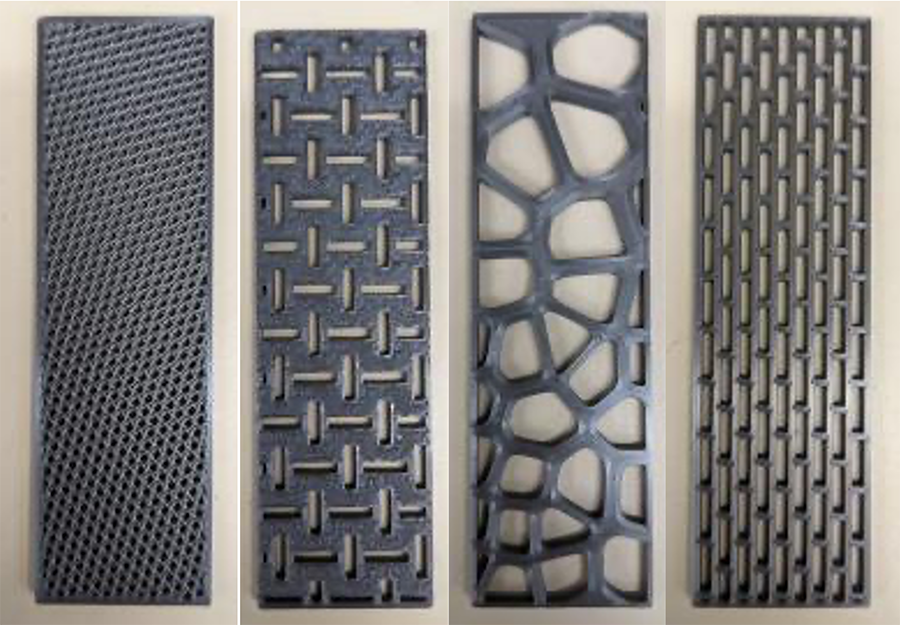
In order to optimize the structural strength of the wrist brace, we 3D printed 3 mm by 30 mm by 100 mm samples for 3-Point Bend Testing and formed braces for Cantilever Bend Testing. The braces were 3D printed identically in every way except for the matrix pattern used. The patterns evaluated were Rectilinear, Hexagonal, Voronoi, PrusaSlicer Hexagonal InfilI at 40% density, Bidirectional (see Figure 2), Triangle, Unidirectional (see Figure 2), and Solid. We tested one sample of each 3D printed matrix for 3-Point and Cantilever Bend Testing. We were also able to 3-Point Bend Test a section of an on-the-market wrist brace with approximately the same dimensions as the 3D printed samples.
3-Point Bend Test
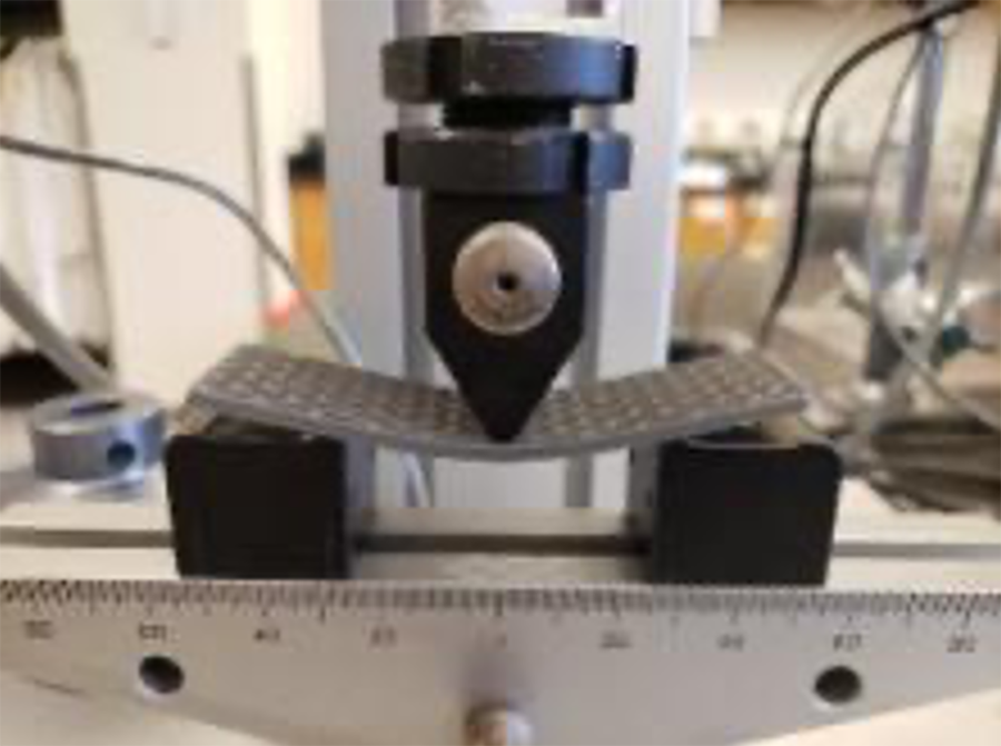
The 3-Point bend test was performed at 23.3°C and test rate and span were set according to ASTM D790-17 standards [6]. The data was collected and the slope of the linear portion of load-deflection curve was collected and used to calculate the modulus of elasticity for each sample. The weight of each sample was collected as well. A representative image of the test setup is shown in Figure 3.
Cantilever Bend Test
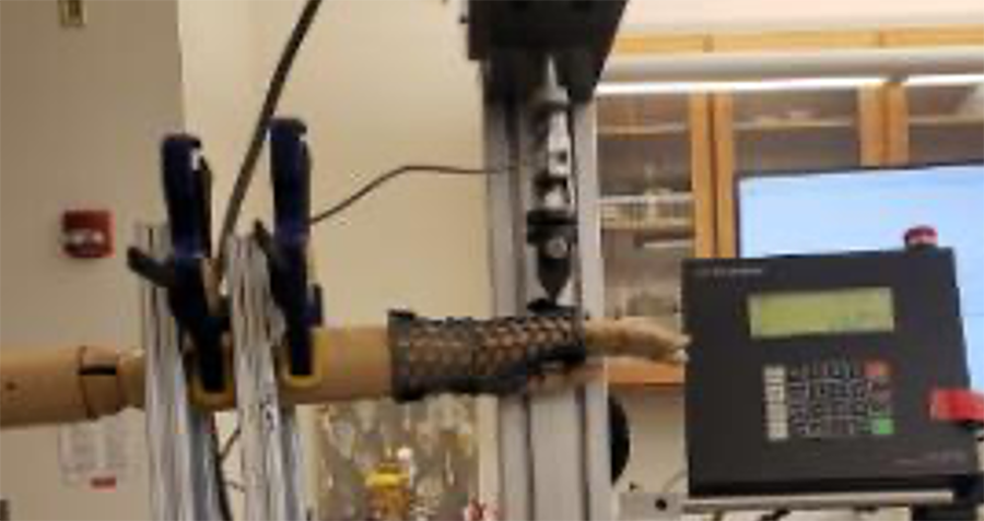
The Cantilever Bend Testing was performed on one formed brace of each matrix. Each formed brace was placed on a jointed manikin of the right arm. The testing was done at 30 mm/min and was done for comparative purposes between prototype designs (Fig. 4).
RESULTS
3-Point Bend Test
| Sample | Elastic Modulus (MPa) | Mass (g) |
| Rectilinear | 0.1000 | 4.0725 |
| Hexagonal | 198.0054 | 3.0649 |
| Voronoi | 387.6929 | 4.8842 |
| PrusaSlicer Infill | 393.4028 | 5.5726 |
| Bidirectional | 404.7068 | 7.5844 |
| Triangle | 534.1435 | 7.5194 |
| Unidirectional | 659.2207 | 5.2367 |
| Solid | 1371.8364 | 10.3679 |
| On-the-Market Brace | 1475.5015 | 16.1879 |
The 3-Point Bend Test yielded a series of load-deflection curves which were used to calculate the Elastic Modulus for each matrix. Elastic Modulus is a measure of how stiff a material is, and a larger elastic modulus indicates that the sample will have less deformation under load [7]. The results are shown below in Table 1.
Cantilever Bend Test
With the cantilever bend test, the force was measured for the duration of the test. For comparison purposes the ratio of force to mass at 40 mm of displacement was calculated. This data is shown in Table 2.
| Sample | Ratio of Force to Mass at 40 mm of Displacement (N/g) |
| Triangle | 1.1427 |
| Solid | 1.8244 |
| Bidirectional | 2.2122 |
| Hexagonal | 2.4984 |
| Unidirectional | 2.7084 |
| Rectilinear | 3.0949 |
| Voronoi | 3.7889 |
| PrusaSlicer Infill | 3.9957 |
The 3-Point Bend Test results in Table 1 indicated that the best design would be a Unidirectional pattern with a fairly high elastic modulus (659 MPa), meaning the brace would be stiff and not deform significantly under load, and low mass (5.2 g) taking into account the desire to minimize overall weight of the brace. However, the cantilever bend offered a more realistic indication of the brace performance. This is because as the brace is molded to the hand, the material stretches, and the material properties change from those present in the flat 3D printed material. These changes are more representative of the final product being tested. Therefore, more value is attributed to the results from the Cantilever Bend Testing.
Table 2 shows that the PrusaSlicer Infill, Voronoi, and rectilinear matrix patterns offer the optimum ratio for mass to force. These criteria were examined most closely due to the desire that the brace can have minimal mass while still fully supporting the wrist throughout the duration of its use and remaining intact. Previous research in the literature also recommended the Voronoi pattern as optimal for structural support [8]. Additionally, this work stated that another factor influencing the success of fabricated orthotic devices was the visual appeal to the user. The organic design of the Voronoi pattern was determined to be aesthetically pleasing. Another consideration to selecting the optimal design is ease of forming the brace to users. The PrusaSlicer infill pattern proved to be the easiest to mold around the wearer's palm, wrist, and forearm using a heat gun. This pattern had a smaller and more uniform matrix than the other patterns. This caused the temperature of the material to rise more evenly, which allowed more consistent curves to be formed around the contours of the hand. The smaller individual units of this pattern also heated up more quickly, which allowed more effort to be focused on the actual molding than on maintaining a high enough temperature in the material.
DISCUSSION
We determined that the optimal designs for the matrix pattern of a 3-D printed wrist brace were Voronoi and PrusaSlicer Infill patterns. This decision was based primarily on the Cantilever Bend Test results and additional information about forming the braces and aesthetic considerations. Our goal is to provide clear instructions and easily accessible materials to allow anyone the ability to reproduce this wrist brace for their specific needs. Previously, we developed an automatic sizing tool for the 3-D printed wrist brace support by using anthropometric measurements of the wrist and mid-forearm [9]. We plan to now use the optimum matrix pattern and attach the machine-learning gesture recognition system developed previously onto the wrist brace [4-5]. This information will be used to update the WristSense project website for this product which details how to fabricate this wrist orthotic through the online user-guide [9]. This project will ultimately lead to a highly customizable and inexpensive wrist orthosis for tetraplegic users to develop using 3D printing and off-the-shelf components.
REFERENCES
[1] National Spinal Cord Injury Statistical Center, NSCISC. 2015 Annual Report Complete Public Version, 106.
[2] Nas K, Yazmalar L, Şah V, Aydın A, Öneş, K. (2015) Rehabilitation of spinal cord injuries. World Journal of Orthopedics, 6(1), 8–16.
[3] Suresh S, Madrinan Chiquito DF, Manda S, Jacob L, Duerstock BS. Motor-activated multi-functional wrist orthotic to assist individuals with cervical spinal cord injuries with activities of daily living. In Proc. of the RESNA/NCART 2016, Arlington, VA, July 10-14, 2016.
[4] Suresh S, Manda S, Marrero C, Jacob L, Duerstock BS. Multifunctional wrist orthotic with universal gesture recognition system, In Proc. of the RESNA 2017 Conference, New Orleans, LA, June 28-30, 2017.
[5] Martin C. (2020) Comparison of Machine Learning Models: Gesture Recognition Using a Multimodal Wrist Orthosis for Tetraplegics, The Journal of Purdue Undergraduate Research: Vol. 10, Article 14. Available at: https://docs.lib.purdue.edu/jpur/vol10/iss1/14
[6] American Society for Testing and Materials. (2017). ASTM standard ASTM D790-17: Standard Test Methods for Flexural Properties of Unreinforced and Reinforced Plastics and Electrical Insulating Materials. https://compass.astm.org/document/?contentCode=ASTM%7CD0790-17%7Cen-US
[7] Woodson RD, "Planning and design of concrete repair," Concr. Struct., pp. 31–38, Jan. 2009.
[8] van Helden, TMN (2020). A laser-cut thermoformed orthosis for distal radius fractures (thesis). Rijnstate, Online.
[9] Duerstock B, Shanghavi A, Suresh S, Will N, Cameron L, Roberts K. (2020). WristSense: Get Your CAD File. WristSense. Retrieved February 22, 2022, from https://engineering.purdue.edu/DuerstockIAS/WristSense
ACKNOWLEDGEMENTS
This work was funded through the Craig H. Neilsen Foundation (#635239). We would also like to acknowledge Dr. Michael Linnes, Emily Bakal, Matt McCormick, and Lauren Cameron for their assistance on the WristSense project. We are grateful to Purdue University and the Regenstrief Center for Healthcare Engineering for their support.