Mandira Marambe![]() 1
1![]() *, Mitchell Sanchez
*, Mitchell Sanchez![]() 1
1![]() *, Juan P. Wachs
*, Juan P. Wachs![]() 2
2![]() , Bradley S. Duerstock
, Bradley S. Duerstock![]() 1,2
1,2![]()
![]() 1
1![]() Weldon School of Biomedical Engineering, Purdue University,
Weldon School of Biomedical Engineering, Purdue University, ![]() 2
2![]() School of Industrial Engineering, Purdue University
School of Industrial Engineering, Purdue University
*Both are co-first authors
INTRODUCTION
Robotic manipulators have the capability to aid human operators in diverse tasks and environments. Applications of high significance have emerged, such as aiding individuals with disabilities [1] [2]. Assistive robotic solutions [2] [3] [4] have shown potential to enhance the autonomy of people with mobility impairments significantly [5] and may also provide cost savings and economic benefits relative to a dependent lifestyle [6] .
Control modalities implemented in assistive manipulator solutions have varied widely depending on the targeted population and tasks. A vast majority of these solutions rely on traditional joystick only or joystick and customized keyboard inputs [2] [7] [8]. Other control modalities explored and implemented have included a head-controlled joystick [9], mouse inputs [10], voice commands [11], eye tracking [12] [13], and cortical motor activity-based control [14] focused mainly on users with disabilities.
Traditional joystick interfaces typically limit the user's control to the direction of motion of the robot and require users to remember complex configurations of button presses, knob twists, and joystick manipulations to shift between control modes. In [15], a haptic device 3D joystick with force feedback to return the joystick to the center after each manipulation was introduced for use by tetraplegics. When the 3D joystick was compared with a traditional 2D joystick with knob rotation and different keyboard control modalities, the 3D joystick achieved a higher performance index and required a shorter learning curve, while keyboard input required less number of operations but took more time to complete tasks.
In this work, two control modes were investigated using a seven degree of freedom (DOF) haptic device configured as a 3D joystick for translational and rotational axes movement. Keyboard inputs were programmed to shift between control mode functions. In addition to providing directional control, this solution also allows for intuitive control of the robot velocity. Additionally, the haptic device is also capable of providing force feedback such as the weight of the object being manipulated to the user during operation.
METHODS
System Architecture
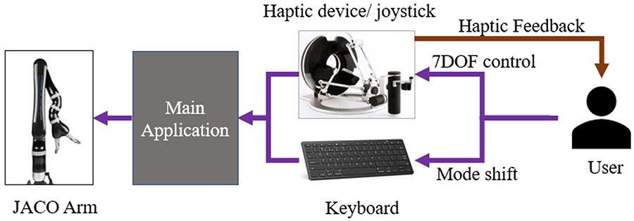
The overall architecture for the control interface is summarized in Figure 1. A Gen2 6DOF JACO arm (Kinova®) [2] was used without the manufacturer-provided joystick. Control inputs to guide the robot is provided through a Force Dimension® Omega 7 haptic device [16] joystick and keyboard presses. Serial communication was established between all devices and integrated in a multithreaded console application on a Windows™ desktop computer.
The hybrid control model implemented in this system was based on previous research as well as user feedback during testing prior to experiments. Building on the tradeoffs and observations discussed by Jiang et al. [15] between a haptic device 3D joystick, a hybrid approach integrating a haptic device joystick and keyboard inputs was implemented in this system. The haptic device served as the motion control input method to guide the robot while keyboard inputs were used for shifting between modes and to carry out other built in single-command motions.
The use of the Omega 7 device facilitated seven degree of freedom control with minimal confusion. The input configuration included seven possible modes. Three modes shifted between X, Y, and Z axis translations while three shifted between rotational axes. Only one rotational mode, that is robot wrist rotation, was introduced to subjects and used in this experiment. The seventh mode was to open and close the gripper. While mode shifts were initiated through keyboard inputs, the translation was performed using the joystick. In all cases, the position of the joystick was mapped to the velocity of the robot translation allowing for easier and more precise control of both robot speed and positioning. For intuitive controllability, the translation axes were mapped to the same axes on the haptic device when viewed from the user's perspective, as were the rotational degrees of freedom. For example, to move the robot end effector left or right (in the x axis), the user had to move the stylus of the haptic device left or right. To rotate the wrist to pour, the user had to rotate their own wrist (and the corresponding degree of freedom on the haptic device) to pour.
To afford intuitive feed variability to the user, the position of the haptic device joystick was mapped to robot velocity. Thus, to manipulate the robot, the user would move the stylus in the desired direction and hold it in one place for the robot to continue moving the in the same direction at a constant velocity. To increase speed the stylus would be moved further in that direction. To decrease speed, the stylus would be moved closer to the center. Therefore, if desired, the user could move the robot faster initially and then decelerate when approaching the target in the same motion of the stylus. The rotational axes were configured the same way, with angular velocity mapped to angular displacement on the haptic device. An origin of between +/- 0.01m and +/- 0.02m in all directions was defined where no motion would occur. This value was fine-tuned on each axis to negate the slight drift of the haptic device. To open and close the gripper, the forward/backward (y axis) translation of the haptic device was used where pulling the stylus backwards mapped to closing the gripper.
To implement speed variability, joystick position was mapped linearly to robot velocity by multiplication coefficients. These coefficients were fine-tuned through empirical testing to achieve enough resolution at a reasonable speed. The set of equations mapping the controller to the robot can thus be defined as:
| (3.1) | |
| (3.2) | |
| (3.3) | |
| (3.4) | |
| (3.5) |
where x represents the left to right motion form the user's perspective, y represents forward and backward and z represents up and down for both the robot and the haptic device,
,
,
are the linear velocities (m/s) of the robot, x![]() j
j![]() , y
, y![]() j
j![]() , z
, z![]() j
j![]() are the positions (m) of the haptic device joystick,
is the angular velocity (rad/s) of the robot joints, w
are the positions (m) of the haptic device joystick,
is the angular velocity (rad/s) of the robot joints, w![]() j
j![]() is the angular positions (rad) of corresponding joints of the joystick stylus (counterclockwise positive for both), and g is the set of angular finger positions (0 at fully closed to 60 degrees at fully open) of the robot.
is the angular positions (rad) of corresponding joints of the joystick stylus (counterclockwise positive for both), and g is the set of angular finger positions (0 at fully closed to 60 degrees at fully open) of the robot.
With this architecture two control modes were implemented. First, a separated or discrete mode was implemented. In this mode movement on each axis is completely separated from all the others. When a user presses a keyboard input for a specific translational axis, for example X, the robot end effector will only move in the X axis, regardless of the input on the stylus in other translational axes.
A continuous control mode was also implemented. In this mode all three translational axes can be controlled at once. For example, if the user selects X on the keyboard they may control the X, Y, and Z movement of the end effector based on the vector displacement of the stylus. In this mode the rotational axis controls remained separated from the controls for the translational axes. Built in keyboard press motions in the system included sending the robot to home position and severing the connection between the joystick and the robot for an emergency stop.
Experimental design
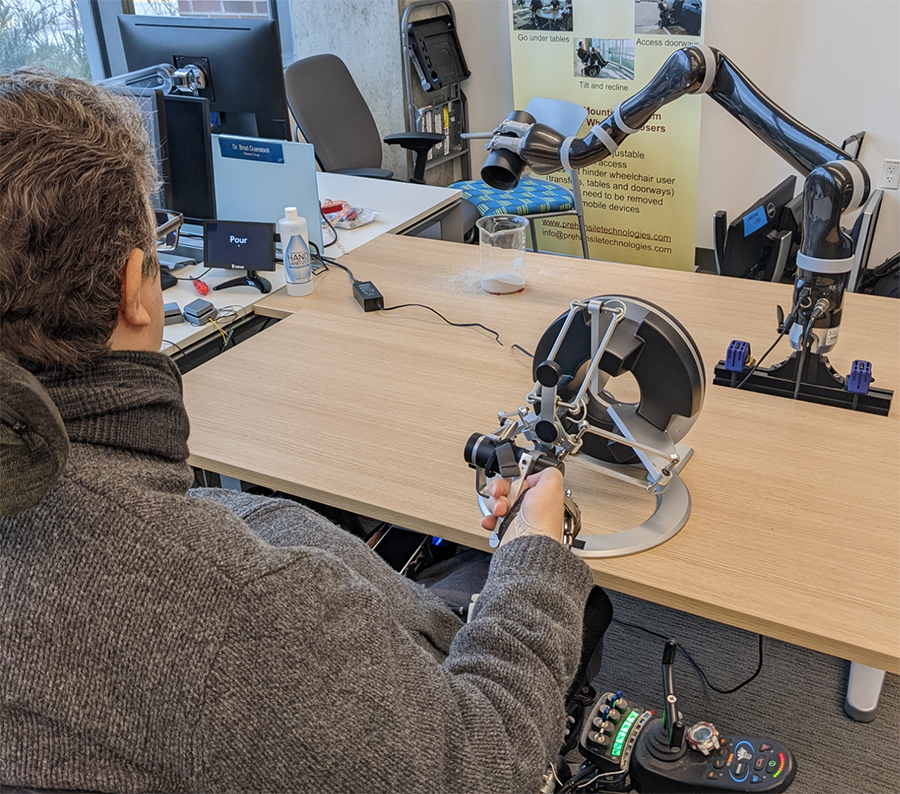
A modified Fitts's targeting task experiment was conducted to evaluate the effectiveness of the two control modes. The modified Fitts's targeting task combined a standard Fitts's task with a pouring task. In this task subjects were asked to do a series of pouring tasks of varying difficulty. In order to vary the difficulty two differently sized target containers were used as well as two locations for the containers to be placed (Fig. 2). Containers with a diameter of 8.5 cm and 12 cm were used. The near and far locations were 25 cm and 55cm respectively from the home position of the robot end effector. In each trial the subject was asked to pour fine grain sand into one of these container and location combinations using either continuous or discrete control mode. Three trials of each combination were conducted for a total of 24 trials per subject with five subjects participating in the study. The order of the selection of the container size, location, and control mode were all randomized.
For each trial data was collected for the completion time, the accuracy, and the number of operations. The accuracy was defined as the percentage of sand that made it from the pouring container to the target container. The number of operations was click save counted as the number of times the subject switch control modes and the number of times the subject started a movement along an axis (i.e. the number of times the controller left the dead zone on any axis).
RESULTS
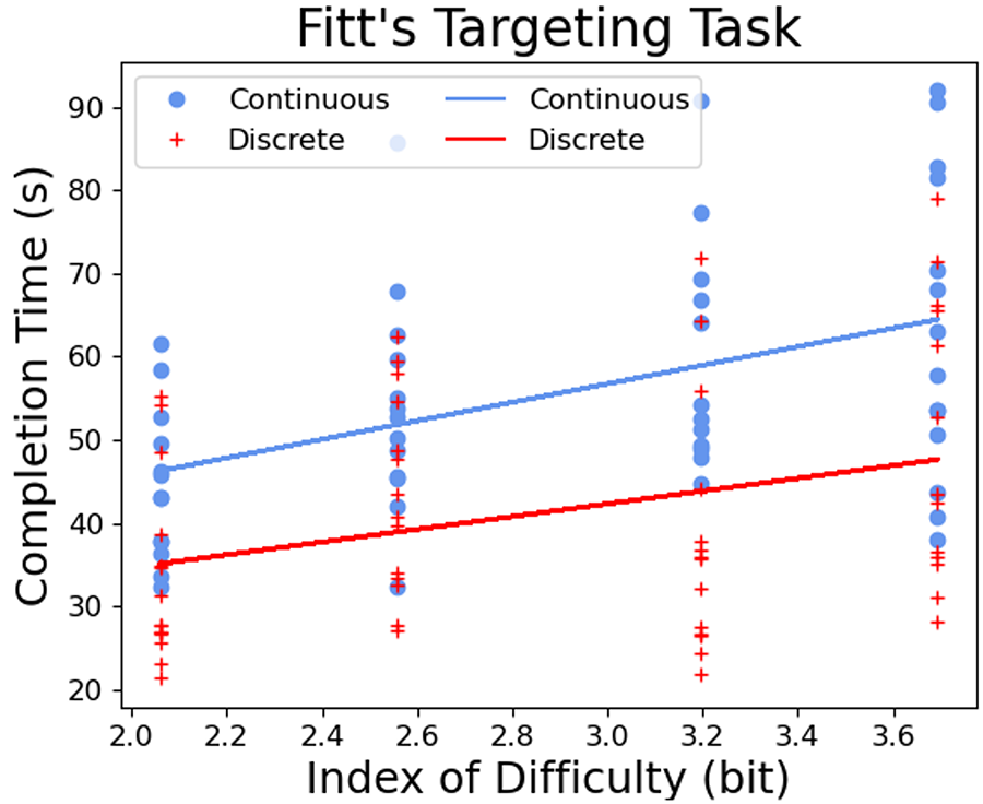
A Fitts's targeting task was chosen to measure a performance index for each control mode. A Fitts's Law result was obtained by plotting completion time versus the Index of Difficulty. With all the points plotted, a linear regression can be performed to get fit lines. The slopes for the fit for continuous and discrete modes were 11.1 and 7.7 respectively. The performance index (PI) is the reciprocal of the slope meaning that the discrete mode had a higher PI. A higher PI indicates a greater rate of human information processing or ease of use (Fig. 3).
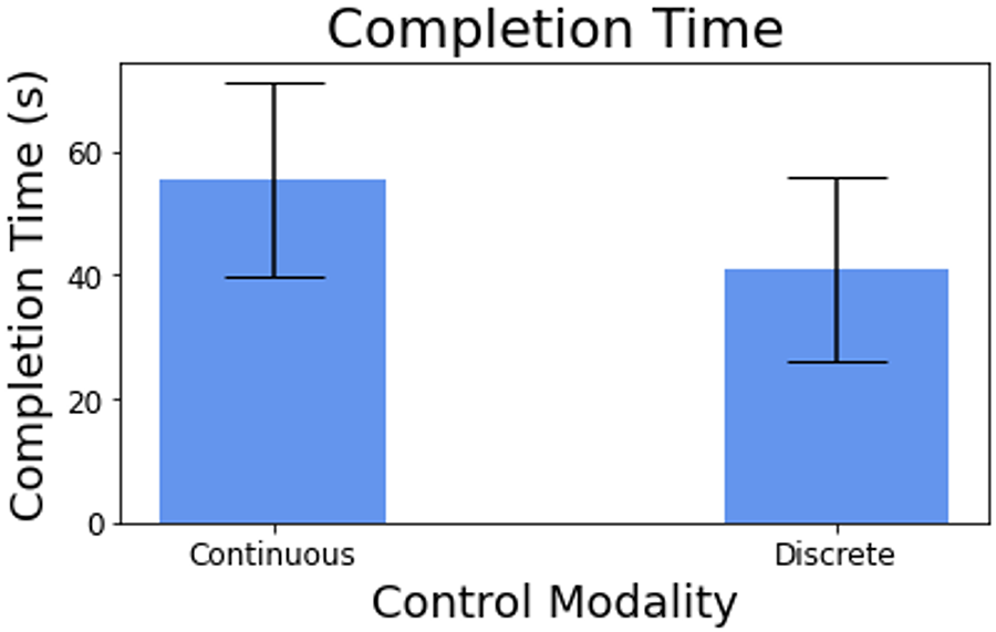
In Figure 4 the average completion time for each control method was compared for the pouring tasks. The average completion time for the continuous mode was 55.5s while the discrete mode averaged only 41.1s.
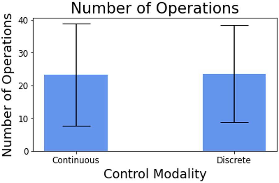
In terms of the number of operations and the pouring accuracy between the two modalities were very similar. The numbers of operations for continuous and discrete modes were 23.2 and 23.5 respectively. The pouring accuracies or percentages of spilled sand were 98.9% and 97.8% respectively (Fig. 5).
DISCUSSION
This paper proposed two control schemes for controlling a robotic arm using a 3D joystick. A pouring experiment was conducted to compare the efficiency of each of the control modalities. It was found that the discrete modality had a higher performance index and lower average completion time while maintaining similar levels of pouring accuracy and number of operations as the continuous modality.
In every one of the metrics that were tested the discrete controller performed similarly or better than the continuous controller. Likely, this is because of the difficulty of making the last fine adjustments in final preparations for the pouring task. The discrete controller provided the user separate control over each axis while not having to worry about accidentally controlling the other axes simultaneously. This allowed the user to make more precise movements in lining up the final pouring motion.
Interestingly, several subjects expressed a preference for the continuous mode over the discrete mode despite the continuous mode having worse performance. Future work could focus on investigating this by measuring the mental load of each of these tasks. Another option would be to allow both discrete and continuous modes to be alternately used during the task. The user would be able to change between the two modes when desired to the benefit of combining the ease of use of continuous mode with the precision of the discrete mode.
REFERENCES
[1] |
U. S. Census Bureau, "Americans with Disabilities:2014," U.S. Government Printing Office., Washington, DC, 2018. |
[2] |
A. Campeau-Lecours and et al., "JACO Assistive Robotic Device: Empowering People With Disabilities Through Innovative Algorithms.," in Rehabilitation Engineering and Assistive Technology Society of North America (RESNA) Conference, 2016. |
[3] |
D. Kim, Z. Wang, N. Paperno and A. Behal, "System Design and Implementation of UCF-MANUS—An Intelligent Assistive Robotic Manipulator," IEEE/ASME Transactions on Mechatronics, vol. 19, no. 1, pp. 225-237, 2014. |
[4] |
F. Farahmand, M. T. Pourazad and Z. Moussavi, "An Intelligent Assistive Robotic Manipulator," in IEEE Engineering in Medicine and Biology 27th Annual Conference, Shanghai, 2005. |
[5] |
S. W. Brose and et al., "The Role of Assistive Robotics in the Lives of Persons with Disability," American Journal of Physical Medicine & Rehabilitation, vol. 89, no. 6, pp. 509-521, 2010. |
[6] |
G. R. B. E. Romer, H. J. A. Stuyt and A. Peters, "Cost-savings and economic benefits due to the assistive robotic manipulator (ARM)," in 9th International Conference on Rehabilitation Robotics (ICORR), Chicago, 2005. |
[7] |
Assistive Innovations, "iArm. https://assistive-innovations.com/en/robotic-arms/iarm. (accessed: Apr. 2021).". |
[8] |
R. Correal and et al., "Human-Robot Coexistence in Robot-Aided Apartment," in Proceedings of the 23rd ISARC, Tokyo, 2006. |
[9] |
Secom, "Secom," 2015. |
[10] |
Y. Shimabukuro, S. Gushi, J. Matayoshi and H. Higa, "Self-feeding assistive 7-DOF robotic arm simulator using solving method of inverse kinematics," IEEJ Transactions on Electronics, Information and Systems , vol. 140, no. 6, pp. 1040-1049, 2021. |
[11] |
B. House, J. Malkin and J. Bilmes, "The VoiceBot: a voice controlled robot arm," in Proceedings of the 27th International Conference on Human Factors in Computing Systems, 2009. |
[12] |
P. Lopes and et al., "ICRAFT-Eye-Controlled Robotic Feeding Arm Technology," 2012. |
[13] |
K. Tanaka, S. Mu and S. Nakashima, "Meal-Assistance Robot Using Ultrasonic Motor with Eye Interface," International Journal of Automation Technology, vol. 8, no. 2, pp. 186-192, 2017. |
[14] |
M. Velliste and et al., "Cortical control of a prosthetic arm for self-feeding," Nature; London, vol. 453, no. 7198, pp. 1098-101, 2008. |
[15] |
H. Jiang, J. P. Wachs, M. Pendergast and B. S. and Duerstock, "3D joystick for robotic arm control by individuals with high level spinal cord injuries," in 2013 IEEE 13th International Conference on Rehabilitation Robotics (ICORR), Seattle, 2013. |
[16] |
Force Dimension, "omega.7," https://www.forcedimension.com/products/omega, Accessed: 2021. |
ACKNOWLEDGMENTS
We are grateful to the Purdue University Regenstrief Center for Healthcare Engineering for its support.