Miriam A. Manary, Kyle J. Boyle, Nichole R. Orton, Brian Eby, Jennifer Bishop, Jingwen Hu, Kathleen D. Klinich1
1University of Michigan Transportation Research Institute
INTRODUCTION
Automated and driverless vehicles (AVs) offer potential for improving independent transportation options for people with disabilities. Many vehicle manufacturers are considering integrated wheelchair stations and seek solutions that allow people seated in their wheelchairs to secure wheelchairs independently in AVs to allow solo travel in a shared, on-call, vehicle fleet. Consequently, there has been renewed interest in the Universal Docking Interface Geometry (UDIG) [1]–[3]. UDIG allows any wheelchair with UDIG-compatible hardware to dock without third-party assistance in any vehicle with a UDIG-compatible anchor. Only the geometry of the interface is standardized, so there are minimal limitations on the design of the wheelchair or the in-vehicle securement system. Because AV fleets are likely to include passenger-sized vehicles, securement system must be crashworthy for high deceleration vehicle environments meaning that many solutions appropriate for large accessible transit vehicles are not robust enough to provide safety in crash events for smaller, lighter vehicles.
Recent research efforts by the University of Michigan Transportation Research Institute [4]–[6] have designed and tested add-on UDIG-compatible attachments for four commercial wheelchairs. This paper summarizes results of successful crash testing of these attachments under frontal and side impact testing conditions, demonstrating the viability of developing UDIG-compatible attachments for wheelchairs that meet current WC19 requirements.
METHODS
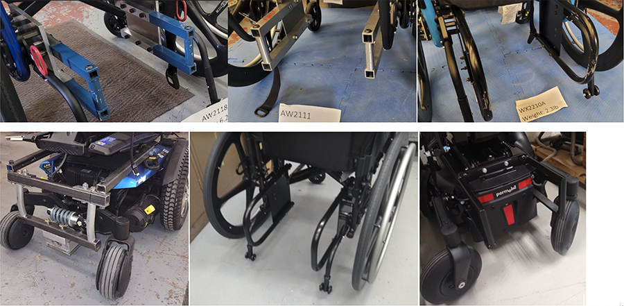
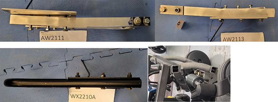
As shown in Figure 1, UDIG-compliant attachments were designed and constructed for four different commercial wheelchairs that had been designed to meet requirements of ANSI/RESNA standard WC19. All the added hardware was included in the original wheelchair footprint and did not increase the size or reduce the ground clearance of the wheelchair. Each set of attachments was connected to the wheelchair near the location of the rear tiedown securement points. Based on feedback from volunteers on the appearance of the first two prototypes, subsequent versions were designed to be less conspicuous, lighter, and more integrated with the wheelchair design.
Crash tests were performed with a heavy-duty UDIG-compatible anchor fixture that allowed measurement of securement loads, developed in an earlier research project [3]. Frontal impact tests used a Hybrid III midsize male ATD, while the side impact tests used an ES2-re ATD. Table 1 contains a matrix of the tests used to evaluate the performance of the prototype attachments. For the Ki Mobility Catalyst 5, three different styles of UDIG were tested to reduce mass and improve appearance.
Test ID |
Wheelchair |
Direction |
Restraint System |
Version + mass (kg) |
AW2111 |
Ki Mobility Catalyst 5 |
Frontal |
Vehicle mounted lap+shoulder belt with pretensioner and load limiter, SCARAB |
K2,1.8 |
AW2113 |
Ki Mobility Catalyst 5 |
Frontal |
Vehicle mounted lap+shoulder belt with pretensioner and load limiter, SCARAB |
K2,1.8 |
AW2115 |
Quantum Rehab Q6 Edge 2.0 |
Frontal |
Vehicle mounted lap+shoulder belt with pretensioner and load limiter, SCARAB |
Q2,4.4 |
ID2201 |
Sunrise Quickie 2 |
Frontal |
Vehicle mounted shoulder belt |
S1, ~1.0 |
ID2202 |
Permobil F3 Corpus |
Frontal |
Vehicle mounted shoulder belt |
P1, 6.2 |
AW2118 |
Ki Mobility Catalyst 5 |
Farside |
Farside vehicle-mounted lap+shoulder belt with pretensioner, CATCH-V' airbag |
K1, 2.9 |
WX2210 |
Ki Mobility Catalyst 5 |
Nearside |
Vehicle mounted shoulder belt, WC-attached lap belt, simulated intruded vehicle interior wall |
K3, 1.0 |
RESULTS
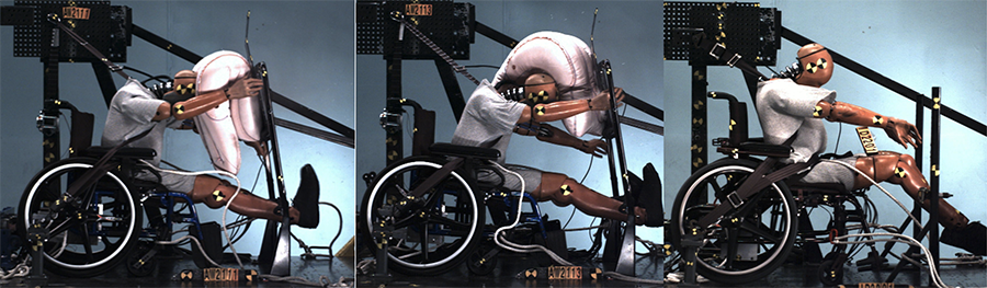
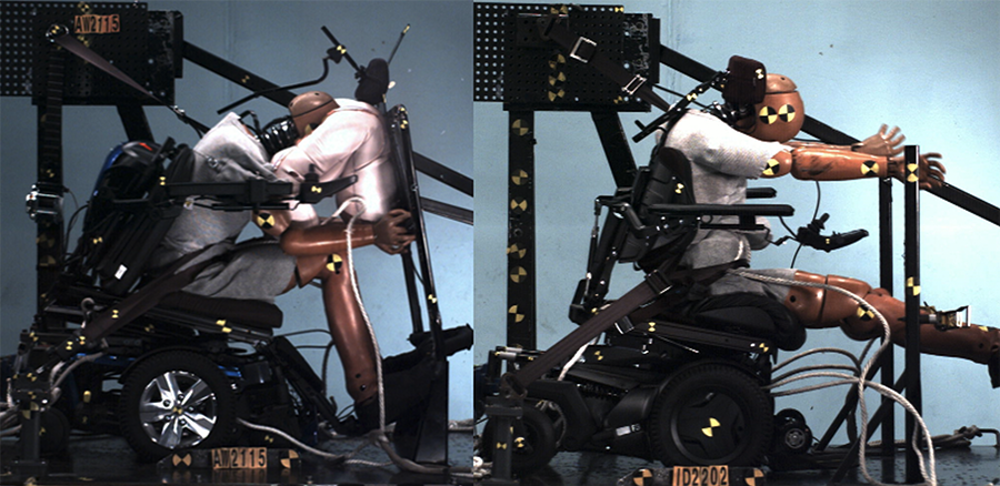
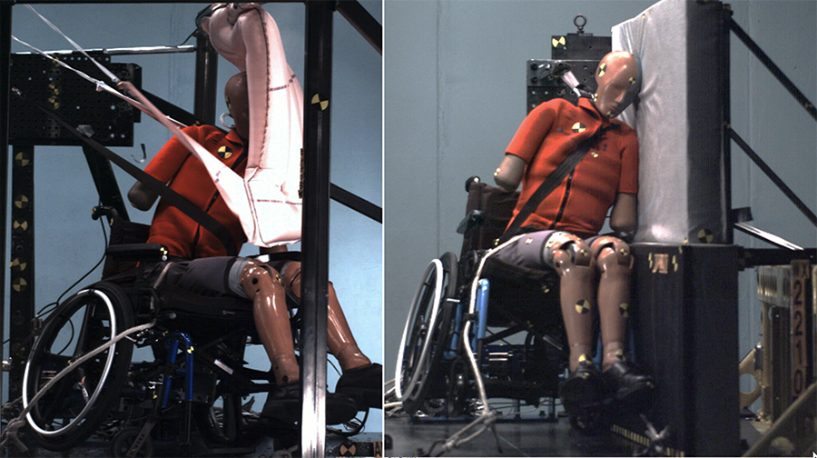
The UDIG attachments performed well in all of the tests. Table 2 shows key ATD and excursion measures for each test; reference values from frontal WC18 performance standards are also included. All of the excursions met the requirements. Figure 2 shows the time of peak excursion for the frontal tests for the manual wheelchair tests, while Figure 3 shows this for the power wheelchairs and Figure 4 shows side impact tests. The lower shoulder belt forces in the AW frontal tests compared to the ID tests comes from using a production seatbelt with load limiter and pretensioner rather than a belt with fixed anchor points. Figure 5 shows posttest samples of deformation.
| Test ID | WC18 frontal limit | AW2111 | AW2113 | AW2115 | ID2201 | ID2202 | AW2118 | WX2210 |
| Crash Direction | Frontal | Frontal | Frontal | Frontal | Frontal | FS | NS | |
| Mean sled decel (g) | 22.5 | 21.6 | 20.9 | 21.0 | 20.3 | 20.8 | 10.2 | |
| Sled delta V (km/hr) | 49.2 | 48.8 | 47.7 | 49.0 | 48.8 | 30.4 | 21.9 | |
| Peak Res Head Accel (g) | 80 | 32.3 | 44.3 | 57.1 | 74.7 | 57.1 | 33.6 | 197 |
| HIC (15 ms) | 700 | 78 | 172 | 231 | 564 | 260 | 82.9 | 675 |
| 3 ms clip Chest Accel (g) | 60 | 37.2 | 31.6 | 44.5 | 41.1 | 44.3 | 28.0 | 22.7 |
| Peak lap belt load (N) | 8819 | 9271 | 7142 | 7850 | 6473 | 3920 | 1508 | |
| Peak shoulder belt load (N) | 4732 | 3580 | 3710 | 9211 | 10724 | 9290 | 1663 | |
| LSLR UDIG Force (N) | 3728 | 3895 | 11804 | 3690 | 16480 | 3032 | 1920 | |
| RSLR UDIG Force (N) | 3569 | 3581 | 10832 | 3095 | 19905 | 7626 | 1632 | |
| LSRR UDIG Force (N) | 4446 | 4055 | 12363 | 3562 | 20589 | 2820 | 1685 | |
| RSRR UDIG Force (N) | 3710 | 3732 | 10218 | 2772 | 15061 | 2899 | 4859 | |
| Forward excursion of Point P | 200 | 32 | 23 | 107 | 75 | 199 | ||
| Forward knee excursion | 375 | 313 | 322 | 189 | 221 | 194 | 627 | |
| Forward head excursion | 650 | 513 | 517 | 510 | 472 | 352 | 440 |
Discussion
Several different styles of UDIG-compatible attachments for four different commercial wheelchair models. Were designed and tested. All of the frontal dynamic tests met the requirements of WC18 for WTORS. While there was some deformation in the attachments post-testing, all of them secured the wheelchair as intended.
The strategy of mounting the attachments near the locations of the rear WC19 securement points was effective. In addition, the attachments were connected to the wheelchair components using standard bolts, indicating that they could be a removable option to fit a user's different transportation needs. On all of the wheelchair models, there were components suitable for mounting the UDIG at the appropriate location specified in the Annex F of WC19.
The initial UDIG designs focused on functionality and strength. Based on feedback on our first designs from wheelchair users, the mass of the attachments on the manual wheelchairs was reduced to 1 kg. Improvements to the appearance of the UDIG hardware were also made so the attachments were less conspicuous and matched with other wheelchair elements.
IMPLICATIONS
This paper demonstrates the feasibility and safety of the UDIG approach to encourage wheelchair, WTORS and vehicle manufacturers to consider this strategy to create transportation options for people seated in wheelchairs where a single wheelchair can be secured independently in a wide variety of vehicles.
References
[1] D. A. Hobson and L. van Roosmalen, "Towards the next generation of wheelchair securement—development of a demonstration udig-compatible wheelchair docking device," Assistive Technology, vol. 19, no. 4, pp. 210–222, Dec. 2007, doi: 10.1080/10400435.2007.10131878.
[2] M. J. Turkovich, L. van Roosmalen, D. A. Hobson, and E. A. Porach, "The effect of city bus maneuvers on wheelchair movement," J Public Trans, vol. 14, no. 3, 2011, doi: 10.5038/2375-0901.14.3.8.
[3] L. van Roosmalen, P. Karg, D. A. Hobson, M. J. Turkovich, and E. Porach, "User evaluation of three wheelchair securement systems in large accessible transit vehicles," The Journal of Rehabilitation Research and Development, vol. 48, no. 7, p. 823, 2011, doi: 10.1682/JRRD.2010.07.0126.
[4] K. D. Klinich, N. R. Orton, M. A. Manary, E. McCurry, and T. Lanigan, "Independent Safety for Wheelchair Users in Automated Vehicles," Ann Arbor, MI, 2022.
[5] K. D. Klinich, M. A. Manary, K. J. Boyle, N. R. Orton, and J. Hu, "Development of an Automated Tiedown and Occupant Restraint System for Automated Vehicle Use," 2021.
[6] J. Hu et al., "Improving protection system for wheelchair-seated occupants in vehicle side impacts," Traffic Inj Prev, pp. 1–6, Aug. 2022, doi: 10.1080/15389588.2022.2114795.