Nichole R. Orton, Miriam A. Manary, Kyle J. Boyle, Brian Eby, Jennifer Bishop, Jingwen Hu, Kathleen D. Klinich1
1University of Michigan Transportation Research Institute
Introduction
The advent of automated vehicles (AVs) holds great promise for improving independent transportation options for people with disabilities. As vehicle manufacturers work to design integrated wheelchair seating stations, they have sought solutions that could allow people who travel in their wheelchairs to dock independently in AVs that also can provide the crash protection needed for smaller vehicles. As a result, there has been renewed interest in the Universal Docking Interface Geometry [1]–[3] specified in current voluntary wheelchair transportation safety standards. With the UDIG concept, any wheelchair with UDIG-compatible hardware should be able to dock in any vehicle with a UDIG-compatible anchor.
Recent research projects conducted by the University of Michigan Transportation Research Institute [4]–[6] have developed multiple versions of prototype UDIG-compatible anchors and wheelchair attachments. These systems, paired with automated belt donning systems, have been installed in a variety of wheelchair station configurations to allow assessment of their usability by volunteers. This paper summarizes key findings that can used to inform design of integrated wheelchair seating stations in automated and other vehicles.
Methods
Different configurations of wheelchair seating stations with UDIG docking securement and automated belt donning systems were evaluated in four different studies. Table 1 summarizes test conditions and Figure 2 shows examples of different layouts. Wheelchair station dimensions were set to the minimum dimensions of 30x48", as well as some wider and longer conditions. An optimal shoulder belt anchor position determined through computational modeling was used in several conditions, as well as variations to evaluate comfort and ease of use. The "practical" setting of condition D represents an anchor located on the vehicle pillar, commonly used in paratransit vehicles. For lap belt anchors, the optimal position identified through modeling was often not feasible in an accessible station. For some conditions, we installed lap belt anchors at the nearest location to optimal. For others, we set the location so that a side-view belt angle of 45 degrees was achieved with either the manual or power wheelchair being used by the volunteers.
| Condition | Vehicle | Station location | Station width (in) | Station length (in) | Seatbelt | Lap Belt | Donning |
| A | Caravan | 2nd row center | 30 | 60+ or 48 | Optimal | Best feasible | A1 |
| B | Caravan | 2nd row, left | 30 | 60+ or 54 | Above Optimal | 45 deg, manual | A1 |
| C | Caravan | 2nd row, left | 30 | 60+ or 54 | Below Optimal | 45 deg, power | A1 |
| D | Caravan | 2nd row center | 30 | 60+ or 48 | Practical | Best feasible | A1 |
| E | BIW | 2nd row, right | 34 | 60+ | IB of Optimal | 45 deg, power | A2 |
| F | BIW | 1st row, right | 30 | 48 | Forward of optimal | 45 deg, power, (IB), higher OB | A2 |
| G | BIW | 1st row, right | 30 | 48 | Rearward of optimal | 45 deg, manual (IB), higher OB | A2 |
| H | BIW | 2nd row, right | 34 | 60+ | OB of Optimal | 45 deg, manual | A2 |
| I | BIW | 2nd, Center | 34 | 60 | Optimal | Best feasible (same as D) | A3 |
| J | BIW | 2nd, Center | 34 | 60 | Optimal | M | |
| K | Transit | 3rd, Left | 30 | 60 | Optimal | Optimal | A4 |
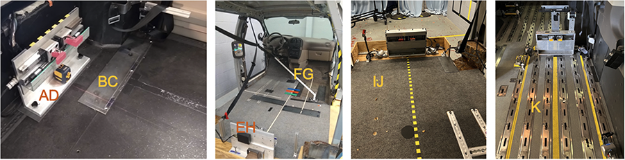
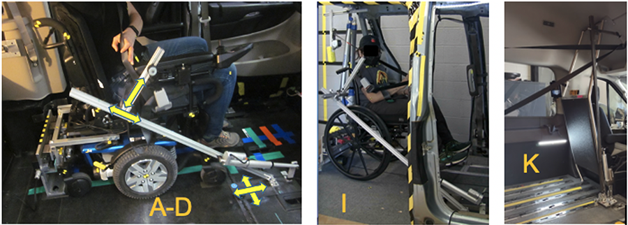
Figure 3 shows the donning arms used. A1 was a rotating arm operated by the volunteer. A2 (shown in the second photo of Figure 2) had two degrees of freedom and was operated by the experimenter for the study. A3 was a similar design to A1. For condition J (also shown in Figure 2) the belt was applied by the volunteer, with the lap belt anchors installed on flexible stalks, and assisted by the experimenter if needed. A4 is a longer version of the A1 design, feasible because of the higher vehicle height.
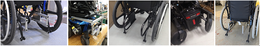
In each study, UDIG-compliant attachments were designed and constructed for five different commercial wheelchairs that had been designed to meet requirements of ANSI/RESNA standard WC19 for crashworthiness. Each set of attachments was connected to the wheelchair near the location of the rear securement points. Figure 4 shows photos of each set of attachments. Based on feedback from volunteers on the appearance of the first two prototypes, later versions were designed to look more integrated with the wheelchair design.
All protocols were approved by the University of Michigan Institutional Review Board. Volunteers transferred to study wheelchairs equipped with UDIG and reviewed a video demonstrating how the system worked. Video recorded them entering the vehicle via ramp or lift, navigating to the wheelchair station, docking the wheelchair, and applying the belt. The experimenter then took photos and 3D measurements of belt fit and posture. The volunteer then doffed the belt, undocked the wheelchair, and exited the vehicle. They answered questions about their experience after each trial. Video analysis documented the time needed to perform each task, as well as any issues experienced by the volunteer using the system.
Results
We had 33 unique volunteers across our studies, including 16 men, 16 women, and 1 not reported. The mean age was 50 years, with a range from 19 to 75. Mean stature was 164 cm, with a range from 107 to 191, while mean BMI was 28.9, with a range from 18 to 56.
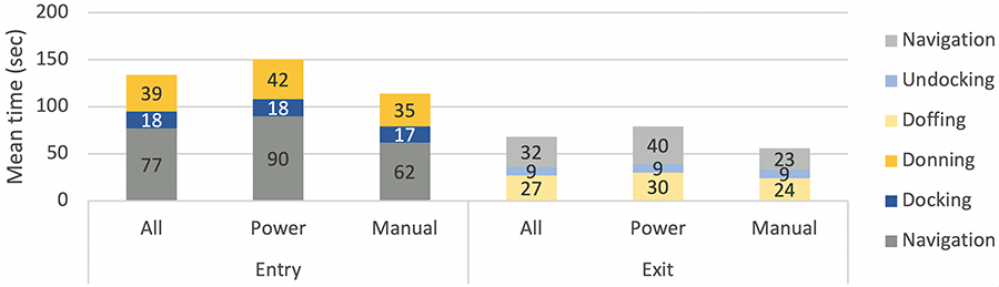
Across all studies, all volunteers were able to successfully secure the study wheelchairs in every trial. Figure 5 shows the average time it took for each phase of the process: navigating between the entry and the station, docking and undocking the wheelchair, and donning and doffing the seatbelt. Mean total entry time was just over 2 minutes, while mean total exit time was just over a minute. Times were longer for trials in power wheelchairs compared to manual, likely because they were longer than the manual wheelchairs and more challenging to maneuver, and because more of our participants were regular manual wheelchair users and less familiar with operating a power wheelchair.
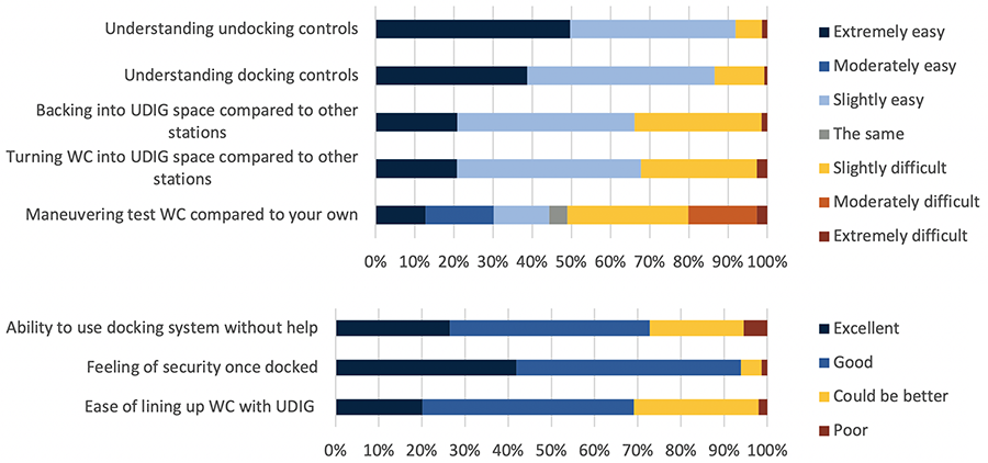
Video analysis indicated that the volunteer faced away from the vehicle during entry in 2% of ramp trials and in 88% of trials with the lift, as recommended for configuration K. In about half of trials, the volunteer moved the seatbelt out of the way while entering, or had it catch on part of the wheelchair. The seatbelt caught on part of the wheelchair while donning in 21% of trials. 37% of participants took 3 or more attempts to align, and 37% required realignment after the first engagement attempt. For exit, 27% had the belt caught on the armrest or push handle while doffing, and the seatbelt caught on the wheelchair or volunteer in 18% of trials as they navigated to exit. In 83% of the trials for second or third row positions, volunteers steered directly out of the station to exit without changing direction. Figure 6 shows volunteer feedback on using the system. For almost all factors, ratings of good/excellent, or some level of easy were reported between 66% and 94% of trials. The exception was the ease of maneuvering the test wheelchair compared to your own, which was considered some level of difficult by over half of participants.
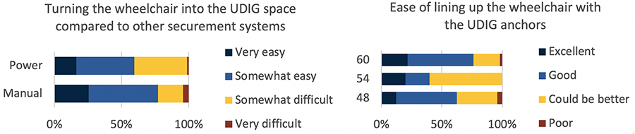
Figure 7 shows how some results vary with test conditions. Trials with the power wheelchairs had higher proportions rated somewhat or very difficult when asked about navigating the wheelchair into the space. For ease of lining up the wheelchair with the UDIG anchors, the longest wheelchair stations had the largest proportion of good and excellent, but the shortest stations unexpectedly had better ratings than the middle length stations.
Discussion
This study demonstrated the feasibility of using UDIG wheelchair securement systems in accessible minivans and vans. The volunteers successfully docked the study wheelchairs using UDIG after viewing a demonstration video. Participants tended to have faster trials when they were using the same type of wheelchair (manual/power) that they used daily. Familiarity with using a particular type of wheelchair complicated identifying how other factors, such as wheelchair station space and location and additional marking, affected ease of use. However, the number of fore-aft movements required to align the wheelchair with the UDIG anchor directly correlated to the amount of fore-aft space provided in the WC passenger area. Stations located closer to the center of the vehicle were generally easier to dock, but had poorer shoulder belt fit if the upper shoulder belt anchor was located on the vehicle C-pillar. Testing one front-row condition showed that with current vehicle dimensions, a shoulder belt upper anchor located on the B-pillar using the minimal required space for a wheelchair station of 48"x30" does not allow acceptable belt fit. Using UDIG in this location is also complicated because it would require a deployable anchor that does not interfere with the side door entry opening and navigation to the seating station.
These studies also evaluated several different belt donning systems. They demonstrated the feasibility of using an automated donning arm that may be necessary if passengers cannot don a traditional seatbelt system by themselves and a driver is not available. Participants were able to navigate around the donning hardware and seatbelts, although sometimes they caught on wheelchair components. Although it provided more clear space to maneuver, the longer belt donning arm used in condition K study placed the belt too close to the person's face as it was lowering the belt when participants were seated in the higher power wheelchair.
Implications
These studies provide insight for vehicle and WTORS manufacturers on how to design wheelchair securement and seat belt systems that can be used by people in wheelchairs without third party assistance.
References
[1] D. A. Hobson and L. van Roosmalen, "Towards the next generation of wheelchair securement—development of a demonstration UDIG-compatible wheelchair docking device," Assistive Technology, vol. 19, no. 4, pp. 210–222, Dec. 2007, doi: 10.1080/10400435.2007.10131878.
[2] M. J. Turkovich, L. van Roosmalen, D. A. Hobson, and E. A. Porach, "The effect of city bus maneuvers on wheelchair movement," J Public Trans, vol. 14, no. 3, 2011, doi: 10.5038/2375-0901.14.3.8.
[3] L. van Roosmalen, P. Karg, D. A. Hobson, M. J. Turkovich, and E. Porach, "User evaluation of three wheelchair securement systems in large accessible transit vehicles," The Journal of Rehabilitation Research and Development, vol. 48, no. 7, p. 823, 2011, doi: 10.1682/JRRD.2010.07.0126.
[4] K. D. Klinich, N. R. Orton, J. Fischer, and M. A. Manary, "Volunteer Evaluation of Wheelchair Accessibility in Vehicles," 2022. Accessed: Dec. 07, 2022. [Online]. Available: https://deepblue.lib.umich.edu/handle/2027.42/174701
[5] K. D. Klinich, N. R. Orton, M. A. Manary, E. McCurry, and T. Lanigan, "Independent Safety for Wheelchair Users in Automated Vehicles," Ann Arbor, MI, 2022.
[6] K. D. Klinich, M. A. Manary, K. J. Boyle, N. R. Orton, and J. Hu, "Development of an Automated Tiedown and Occupant Restraint System for Automated Vehicle Use," 2021.