Holly Wilson-Jene, M.S.![]() 1,2
1,2![]() , Joseph Ott, M.S.
, Joseph Ott, M.S.![]() 1,2
1,2![]() , Jonathan Pearlman, Ph.D.
, Jonathan Pearlman, Ph.D.![]() 1,2
1,2![]()
![]() 1
1![]() University of Pittsburgh, Pittsburgh, PA, United States,
University of Pittsburgh, Pittsburgh, PA, United States, ![]() 2
2![]() International Society of Wheelchair Professionals, Pittsburgh, PA, United States
International Society of Wheelchair Professionals, Pittsburgh, PA, United States
INTRODUCTION
Manual wheelchair users are at a high risk of upper extremity (UE) injury, including rotator cuff injury [1,2], due in-part to continual daily activity involving propulsion of their wheelchair. These injuries can lead to reduced activity and challenges in daily life for manual wheelchair users (MWU). [3] Rolling resistance is the primary force acting against propulsion forces for manual wheelchair users (MWU). For clinicians, it is important to understand how manual wheelchair equipment selection, setup, and maintenance can impact rolling resistance (RR) for MWU. Adjustments in rear axle position changes the load on the rear wheels and consequently changes RR. [4] Other parameters such as toe, camber, tire type, and tire pressure of the rear wheels can also affect RR. [5] [6]
The goals of this study were twofold. First, we performed a community-based study to better understand the prevalence and severity of factors that could lead to increase RR for MWU, including misalignment of the rear wheels (measured by toe-in/out and slop), camber, and tire/wheel selection. Second, we performed laboratory testing using a drum-based RR testing machine to accurately measure the influence of the factors that we found in the community. This paper builds on previous work developing a novel, drum-based RR testing equipment and evaluating factors influencing RR forces for manual wheelchairs [7], to support improved product design, selection, and setup.
METHODS

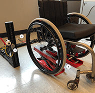
A community-based study was conducted with manual wheelchairs, collecting manual wheelchair characteristics, use conditions, and wheel and caster measurements. A laser measurement system shown in Figure 1, was utilized to measure within +/- 1 mm accuracy the distance across the wheels, measured at axel height. Toe angle was calculated from measurements of distance across wheels relative to the wheel diameter, using the equation [Toe angle = inverse sin (difference of the distance between wheel divided by wheel diameter)]. Slop (excessive play in the axle) was calculated in the same manner, from measurements of wheel distance while the wheelchair was raised, using 1 lbf. constant force springs applying pressure to the rear wheels to induce toe in and toe out. Camber measurements were obtained using a 4 foot digital level on the push rims. The floor slope was also measured, and camber results were adjusted for floor slope. The study was deemed IRB exempt and criteria for participants included: MWU over 18 years of age, wheelchair width between 14 and 32 inches wide and participant weight less than 300 lbs. The questionnaire and measurements were collected on a tablet using a cloud based online survey system. [8]

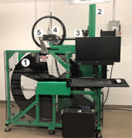
In a laboratory setting, drum-based testing of RR was conducted to quantify the impact of current wheelchair misalignment, the influence of various factors, and any interaction effect of factors. The drum-based testing machine was designed and built at the University of Pittsburgh, and is shown in Figure 2. [7] A four foot drum (1) rotates at constant speed. The upper frame (2) supports the arm (3) (consisting of parallel precision ground one and a half inch rods tangent to the drum) which supports four air bushings (4). Compressed air pumped into the bushings causes them to float frictionless on the rods. The load cell, mounted on the front of the arm, measures pullback force (FRR) on the truck, a direct measurement of RR. Tire type, tire pressure, toe, camber, load, surfaces, and casters type can all be varied independently.
RESULTS
The community-based study resulted in recruitment of n=200 individuals primarily from adaptive sporting events (82%). To ensure the correct sample population was measured, specific questions about wheelchair use were included. Manual wheelchairs were reported as the primary means of mobility for 92% of participants and 96.5% of all participants were self-propelled. Review of the manual wheelchair makes and models evaluated showed that the majority are classified under HCPCS code of K0005 "Ultralightweight" as summarized in Table 1. Discussion with a clinician revealed the majority (94%) of the K0005 category would have previously been categorized as K0009, "rigid custom", which was eliminated in 2013.
| Frame Description | HCPCS | N | (%) |
|---|---|---|---|
| Ultralightweight | K0005 | 176 | (88.0) |
| High Strength lightweight | K0004 | 11 | (5.5) |
| Other | Various | 13 | (6.5) |
The most common brand wheelchairs were TiLite (45.5%), Quickie (20%), Per4max (10.5%) and Invacare Top End (9.5%). The most common wheels were Spinergy (52.5%), Standard Lite-Spoke (various manufacturers) (26.5%), and other which included mag wheels, X-Core, carbon fiber, power assist and a few unknown type (21%). High pressure pneumatic tires (maximum pressure > 100 psi) were the most frequently observed, representing 54%, with Schwalbe Marathon Plus Evolution (MPE) the most common tire, accounting for 34.5% of all tires. Solid or airless inserts comprised 18.5%, and lower pressure (<100 psi) represented 18%. Some tires could not be categorized based on a lack of markings or information from the MWU. Other wheelchair information, use data, and measurements were obtained.

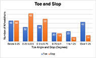
Toe and slop were calculated from laser-based wheel measurements, and the results are grouped by increments of toe angle in Figure 3. Of the 200 wheelchairs measured, the average toe angle was 0.92, the average slop was 0.61 degrees, and the combined average toe and slop was 1.53, or 0.765 degrees of toe for each wheel. One third of wheelchairs had more than 1 degree of toe, and 12% had more than 1 degree of slop. Higher levels of toe did not correlate with increased slop. There were three outliers for toe and slop, which were included except where noted. Combining toe and slop, 22% of wheelchairs had levels of toe or slop greater than 1.5 degrees. Two wheelchairs (1%) had both toe and slop greater than 1.5 degrees.
| Wheelchair Age | N (%) | Average Toe | Average Slop *excludes outlier data |
|---|---|---|---|
| < 1 year | 27 (14%) | 0.89 | 0.44 |
| 1-2 years | 42 (21%) | 0.85 | 0.45 |
| 3-4 years | 50 (25%) | 0.78* | 0.58* |
| >4 years | 79 (40%) | 0.89 | 0.60* |
Information on the age of the device was collected in the following categories: less than 1 year, 1-2 years, 3-4 years or greater than 4 years old. Slop was higher for manual wheelchairs over 3 years of age than for newer wheelchairs. Toe had no correlation to the age of the device (Table 2).
Camber measurement results yielded average camber of 2.95 degrees for the left wheel and 3.05 degrees for the right wheel. The distribution of camber measurements shows the majority of measurements falling between 2 and 4 camber (59% on left and 54.5% on right). Drum-based rolling resistance testing showed camber to have only a modest effect on rolling resistance forces with higher degrees of camber increasing RR.

Tire pressure measurements on 50 wheelchairs were obtained. Of these tires, high pressure pneumatic tires (maximum pressure > 100 psi) made up 50% of the samples and 42% were airless or solid tires.
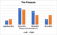
Tire inflation distribution is illustrated in Figure 4, and the average inflation measured was 41.6% for left side and 40% for right side of the max pressure of the tire. Importantly, the majority of wheelchairs (52%) had less than 40% tire inflation and no tire inflation measured was over 80%.
Drum-based rolling resistance testing at 1.5 degrees of toe corresponds to 84% increased rolling resistance for Schwalbe Marathon Plus Evolution (MPE) high pressure pneumatic tires, the most prevalent tire observed in the field study. The RR increase for airless insert tires was 34% and 109% for lower pressure pneumatic (Pr1mo Orion) at 1.5 degrees. Table 3 illustrates the percentage changes in RR related to toe angle. It important to note that while the airless insert was less susceptible to increases in RR due to toe, it had an overall higher RR values compared to the other tires.
| Toe Angle | High pressure pneumatic (MPE) | Airless Insert | Lower pressure pneumatic |
|---|---|---|---|
| -2 | 131.1% | 61.3% | 183.9% |
| -1.5 | 83.7% | 34.4% | 108.9% |
| -1 | 43.3% | 16.7% | 48.9% |
| -0.5 | 10.6% | 1.5% | 7.9% |
Rolling resistance increases parabolically as toe angle increases, with second order polynomial best fit lines most accurately predicting the rolling resistance increase. Higher levels of toe or slop result in more significant increases in rolling resistance and potential impact on upper extremity for injuries.
The range of conditions observed from the field study were evaluated on a drum-based machine to evaluate rolling resistance for toe, camber and tire pressure. These parameters were correlated to equivalent weight added, by looking at the absolute increase in RR and comparing this to increases seen with increased weight as tested on the drum-based test equipment. Using best fit lines of rolling resistance versus load, the equivalent load was estimated as shown in Table 4 below.
| Measurement | Average | Standard Deviation | Equivalent Weight Added |
|---|---|---|---|
| Toe (mm) | 9 | 12 | 24 lbs. |
| Toe (Degree) | 0.9 | 1.2 | |
| Slop (mm) | 6 | 8 | 5 lbs. |
| Slop (Degree) | 0.6 | 0.8 | |
| Camber (Degree) | 3.0 | 1.5 | 7 lbs. |
| Tire Pressure | 40% | 20% | 20 lbs. |
DISCUSSION
This study has explored prevalence of toe, slop, tire inflation as well as wheelchair characteristics and use patterns. The participants were primarily active, self-propellers, and their primary means of mobility was their wheelchair. The make and models of the wheelchairs can be categorized primarily as K0005 ultralightweight, which includes those formerly under the rigid custom K0009 category.
The results showed very low tire inflation (average 40%), significant toe and slop (average 1.53 degrees), and average camber of 3 degrees. Rolling resistance testing of these factors individually and combined indicated an additive effect for each factor and estimates for these conditions are outlined in Table 4. Small increases in toe combined with low tire pressure can translate to significant increases in RR.
Although tire pressure inflation was not measured on all wheelchairs, it revealed a significant issue. Many participants were unaware of their low tire inflation levels until it was checked. These results indicate a need for increased awareness of tire inflation issues for manual wheelchair users. High pressure pneumatics were the most frequently observed tire, and drum-based testing results showed that even partially inflated (40%) pneumatic tires (high and lower pressure) still have lower RR compared to airless insert tires. Many participants utilized airless inserts or solid tires, which eliminates many maintenance issues, but is accompanied by higher resistance to propulsion forces. Clinician awareness of tire inflation issues could lead to more focus and education on the importance of product prescription and maintenance to MWU.
For toe angle, the field study found that new wheelchairs are just as likely as older wheelchairs to have significant levels of toe. Although age of the device does not correlate to toe angle, slop does show correlation with age, and manual wheelchairs over 3 years old had higher levels of slop than newer wheelchairs. Most wheelchairs do not have a specific adjustment mechanism to modify or change toe angle or slop. In addition, there is not currently a simple clinical tool for measuring toe angle or slop for wheelchairs. Potential areas where slop can arise includes part tolerances, axel to bearing or axel to axel tube connections, and bearing wear. Some causes of slop have potential mitigation through maintenance and/or product design and setup. A significant number of wheelchairs (22%) were found to have more than 1.5 degrees of slop and/or toe. For clinicians, the awareness that toe angle can be present in both new and older wheelchairs, and that slop can increase over time, is important. Maintenance or other approaches such as design improvements could be investigated further.
REFERENCES.
- Burnham, R. S., May, L., Nelson, E., Steadward, R., & Reid, D. C. (1993). Shoulder pain in wheelchair athletes: the role of muscle imbalance. The American journal of sports medicine, 21(2), 238-242.
- Sie, I. H., Waters, R. L., Adkins, R. H., & Gellman, H. (1992). Upper extremity pain in the postrehabilitation spinal cord injured patient. Archives of physical medicine and rehabilitation, 73(1), 44-48.
- Curtis, K. A., Drysdale, G. A., Lanza, R. D., Kolber, M., Vitolo, R. S., & West, R. (1999). Shoulder pain in wheelchair users with tetraplegia and paraplegia. Archives of physical medicine and rehabilitation, 80(4), 453-457.
- Cowan, R. E., Nash, M. S., Collinger, J. L., Koontz, A. M., & Boninger, M. L. (2009). Impact of surface type, wheelchair weight, and axle position on wheelchair propulsion by novice older adults. Arch Phys Med Rehabil, 90(7), 1076-1083. doi:10.1016/j.apmr.2008.10.034
- VanderWiel, J., Harris, B., Jackson, C., & Reese, N. (2016). Exploring the relationship of rolling resistance and misalignment angle in wheelchair rear wheels. RESNA, Arlington, VA, 12.
- Sawatzky, B. J., Kim, W. O., & Denison, I. (2004). The ergonomics of different tyres and tyre pressure during wheelchair propulsion. Ergonomics, 47(14), 1475-1483. doi:10.1080/00140130412331290862
- Ott, J.E., Marcus, M.M, Lee, L.C., Pearlman, J.L (2019). Preliminary results of wheel rolling resistance using a drum-based testing machine, RESNA, Arlington, VA,
- Qualtrics online survey research tool
ACKNOWLEDGEMENTS
The paper was supported by the following: Improving Health and Function Through Use of Performance Standards in wheelchair Selection Grant #: 90REGE0001-02-00, National Science Foundation Integrative Graduate Education and Research Traineeship award number IGERT 1144584, and U.S. Agency for International Development through Agreement Nos. APC-GM-0068, SPANS-037, APC-GM-0107, and FY19-A01-6024. A special thank you to the Human Engineering Research Laboratories for the use of their facility to build the testing machine and feedback along the way. Also, a thank you to the International Society of Wheelchair Professionals (ISWP) standards working group for their continued support of this research and helpful advice. Thank you to Travis Henderson, M. Mendel Marcus, and London Lee for design and development work for testing equipment used in this study.