Katsutoshi Oe![]() 1
1![]() , Mutsuhiro Nakashige
, Mutsuhiro Nakashige![]() 2
2![]() , Ryota Shibusawa
, Ryota Shibusawa![]() 1
1![]()
![]() 1
1![]() Daiichi Institute of Technology (Kirishima Japan),
Daiichi Institute of Technology (Kirishima Japan), ![]() 2
2![]() Shonan Institute of Technology (Fujisawa Japan)
Shonan Institute of Technology (Fujisawa Japan)
INTRODUCTION
Individuals who undergo laryngectomy as a radical treatment for laryngeal cancer lose their vocal cords and their voice; this also occurs with individuals suffering from ALS (amyotrophic lateral sclerosis) when they are fitted with a respirator.
When voice, which depends on the vocal cords and laryngeal functions, is lost, individuals are deprived of speech, their most important communication tool. This often causes acute mental distress. This has prompted research on speech product substitutes (SPSs), and some SPSs are used practically. However, they have problems with voice quality, articulation, and intonation. For example, the electrolarynx uses an electro vibrator as their lost sound source, and this method has good features of voice continuity, sound volume, and acquisition.
On the other hand, the electrolarynx has poor voice articulation because of its uncontrollable pitch frequency. To solve this problem of the electrolarynx, many pieces of research about the control method for electrolarynx are being conducted: Goode [1], Uemi [2]. Goldstein used the electromyographic (EMG) signal to control the on-off of an electrolarynx, but the pitch frequency could not control [3]. All of these techniques focused on controlling the pitch frequency. However, these control methods did not use the laryngeal muscle signals that control the pitch in normal subjects. Our research aimed to develop a novel SPS with high controllability.
In our previous research, it was clarified that the myoelectric signal of the sternohyoid muscle (SH) could control the on/off of the electrolarynx [4]. Furthermore, we tried to control the three-step (Hi, Mid, Low) pitch frequency control, and got the result that the exponential was a suitable conversion function, but its control accuracy was not high enough for practical use for some test subjects [5]. In this report, we try to control the electrolarynx by two steps with linear, quadratic, and exponential conversion functions, and the results of its control accuracy are described. Finally, the results are compared to that of three steps control.
CONTROLLABLE ELECTROLARYNX
Our myoelectric control-type electrolarynx contains an EMG electrode, a GND electrode, an electrolarynx with control input, and a control unit for signal processing and driving. The myoelectric signal is measured by an EMG electrode attached to the human neck surface near the SH. To get the stable signal, this control unit has the GND electrode attached to the wrist of the test subject.
The important terms for muscles that are used as the control signal sauce of an artificial larynx are as follows: 1) activation at phonation (for on-off control); 2) control of vocal cords tension (for pitch frequency control); and 3) shallow location (for detection by a surface EMG electrode).
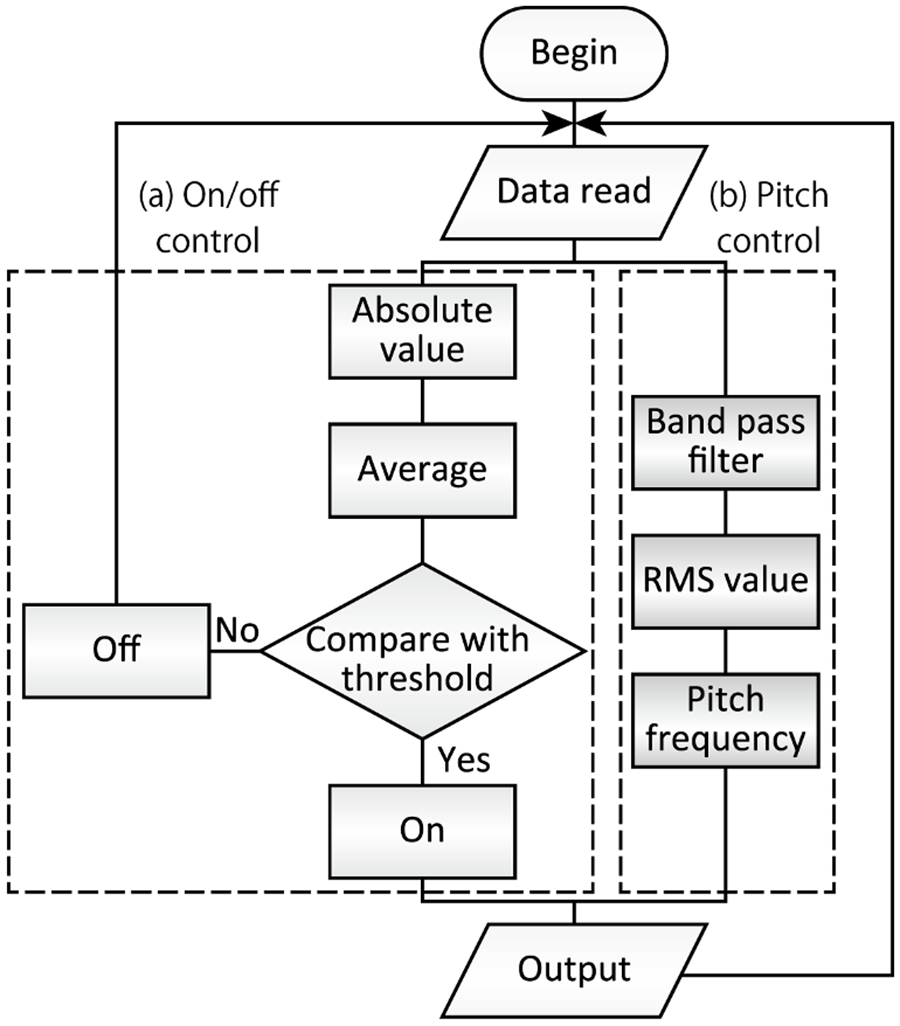
From the above-mentioned conditions, we choose the SH. The flowchart of the electrolarynx is shown in Figure 1. This system is constituted from mainly two flows, (a) on-off and (b) pitch frequency flows. The on-off control was described in our previous report [4].
To control the pitch frequency, the measured EMG signal is filtered by the bandpass filter, and its RMS (Root Mean Square) value is calculated. The RMS value is translated to control signal for pitch frequency, output to the electrolarynx. For unrestricted frequency control, the conversion function for the RMS value to the pitch frequency is very important. In this report, we describe that the proposal and evaluation of the new control parameter.
In our previous research, we tried to evaluate the control performance of the following conversion functions from the viewpoint of control accuracy: linear, quadratic, and exponential. And we got the result that the suitable conversion function was exponential, its control accuracy for three-step pitch frequency control by 7 test subjects was 83 to 97% [6].
EVALUATON OF TWO-STEP PITCH FREQUENCY CONTROL
Is a three-step control necessary?
The lowest value of three-step control accuracy is 83%, this value is not so high to use commercially. Some medical doctors and electrolarynx users advised that three levels of control were excessive and two levels were sufficient. Therefore, the control accuracy of two steps control is evaluated and it is compared to that of three steps control.
Evaluation of two-step control
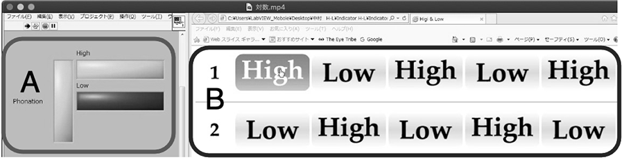
To evaluate the controllability of the frequency control, the indication of the test subject's intention and the tone from the converted EMG signal were compared and the errors were counted. The interface set-up is presented in Figure 2.
This interface is composed of vocalized sound indicator (left side) and an intention indicator (right side). The intention indicator has tone indicator functions. The test subject indicates the intention indicator of "High" and "Low" by the mouse pointer with his intention. At the same time, he is conscious of generating EMG signals. The vocalized sound indicator lights up according to the generated EMG signal. In case of the difference between the left and right indicators from captured video movie was occurred, this was counted as an error (30 fps). The test subjects were three 22-year-old healthy males.
Results and Discussions
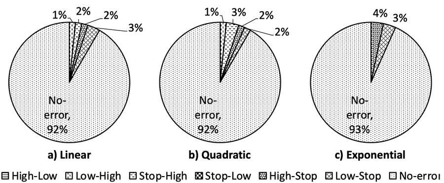
One of the error rates at tone change by two-step control is shown in figure 3. From the result, it seemed that the error rate of the linear and the quadratic (8.3% each) had a little inferior value to that of the exponential (6.7%).
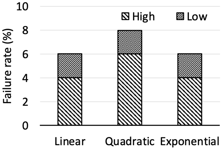
To evaluate the control stability, the numbers that the subject failed to keep the constant tone were counted and calculated the failure rate. The result is shown in figure 4. From this result, the failure rate of exponential (6%) had a similar or little bit superior value to that of the other two functions (6% for linear, 8% for quadratic). Therefore, it was clarified that the superiority of the exponential function had was only a little in the case of two-step control.
To compare with the result of two-step and three-step, it was clarified that the two steps control has higher control accuracy than that of three steps. In the three steps control, the generation and keeping of "mid" tone are very difficult, because a signal of appropriate strength is required without being too strong or too weak. On the other hand, the two steps control does not need to generate the "mid" tone, then this high accuracy is natural. Regardless of the control function, the control accuracy is over 90% through three test subjects. Therefore, it is considered that the two-step control has enough controllability for practical use.
CONCLUSION
In this paper, we proposed the two steps control for our controllable electrolarynx and evaluated its performance. From the results, the following have been concluded.
1. The two-step control had higher control accuracy than the three-step control.
2. The high control accuracy of the two-step control did not matter the type of control function.
REFERENCES
- Richard LG, Artificial laryngeal devices in post-laryngectomy rehabilitation, Laryngoscope, 1975, 85(4):677-689.
- Norihiro U, Toru I, Makoto T, Jun-ichi M, Proposal of an electrolarynx having a pitch frequency control function and its evaluation, Trans. Inst. Electrom. Inf. Commun. Eng., 1995 J78-DII(3):571-578.
- Ehab AG, James TH, James BK, Garrett BS, Robert EH, Design and implementation of a hands-free electrolarynx device controlled by neck strap muscle electromyographic activity, IEEE Trans. On Biomed. Eng., 2004, 51(2):325-332.
- Katsutoshi O, Toshio F, Development of the artificial larynx with neck EMG signal control, Proc. of 2010 Int. Symp. on Micro-NanoMechatronics and Human Science(127-132). Nagoya; 2010.
- Katsutoshi O, Development of controllable artificial larynx by neck myoelectric signal, Procedia Engineering, 2012, 47:869-872.
- Katsutoshi O, Shohei K, Ryoya N, Proposal of new control parameter for neck myoelectric control-type electrolarynx, Proc. of 2017 Int. Symp. on Micro-NanoMechatronics and Human Science, 2017, 127-132
ACKNOWLEDGEMENTS
This work was performed within JSPS KAKENHI Grant Number JP17K01602, JP20K11226.