Design of a Terrain-Capable Walker-Wheelchair with Torso Support
Ryan D Goettl (Midwestern University Glendale AZ)*; Timothy Ammon (Midwestern University Glendale AZ); Catana Brown (Midwestern University Glendale AZ)
ABSTRACT
It was identified that there are unmet needs in the medical industry for low-cost assistive devices such as walkers, gait trainers, and wheelchairs with features such as terrain versatility, torso support, and easy maintenance. The device design proposed in this paper addresses these needs in a single product with high performance and cost-effective design choices.
In this paper we discuss the overall design of a combined walker-wheelchair device. This is followed by an analysis of system stability with multiple approaches. The paper also explains how and why the simulations were conducted to imitate realistic conditions and how they approximately test for real risk of failure.
INTRODUCTION
Over 6.8 million people in the United States use devices for walking assistance. [1] This group includes 1.7 million wheelchair riders, and 6.1 walking device users, such as those using canes, crutches, and walkers. [1] Walking aids improve several aspects of overall well-being, such as improved bowel function and bone density, as well as outcomes such as increased motivation and social activity [2].
Immobility has large costs to society, the economy, the environment, and each individual who suffers from it. In low-income areas (LRS) the problem is much worse, as while less than 1% of medical devices are out of service in resourced areas (RS), more than 80% of all medical supplies in LRS are donated [3].
To make a small step to lessen this impact for some individuals, this study designed a low-cost walker-wheelchair system to help individuals who can benefit from a wheelchair-walker system. The design seeks to help both those who use wheelchairs and walkers to live fully functional and joyful lives. This design is intended for children.
The design of the walker was based on what was revealed by research to be a market gap. A clinician was interviewed to assess market gaps related to care of disabilities with walkers and gait trainer devices. From this interview and a literature search, it was found that there is a need for a walker that combines several features currently only found in separate devices. Thus, this product was designed to address the need for a gait trainer that enables the following features in one product: variable weight support and trunk support, enabling hands to be free or unused; rough terrain durability; low cost; a seat that comes from behind, brakes; and easy maintenance such that the device could be repaired with materials that could be found in a bike shop.
DESIGN AND METHODS
Overall, this study consisted of four parts. First, an analytical approach is taken to optimal conceptual product design. Second, constraints are determined based on research and calculations. Third, using CAD and dynamic multi-body simulation software, a virtual model is built and tested. Finally, the design and simulation results are analyzed and prepared for use in a prototype.
Description of concept selection
Concept selection was developed through brainstorming, starting from a unified interest in creating a walking solution for low resource communities. Design attributes were decided using a matrix to weigh customer needs with practical and physiological constraints. Overall, there was an objective of maintaining simplicity and minimizing components, while providing the most important functionality features in a walker. A market search and benchmarking with these market products was performed to compare our product to what is already readily available.
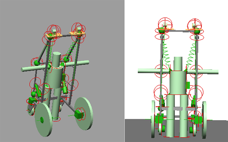
The result is a wheelchair-walker enabling those with low upper body strength to walk, or a person of a lower severity disability be able to use their hands while standing, as shown in Figure 1. There was consensus of the need to design something for a population that is underprivileged. With this in mind it was decided to design a walker that is affordable and sustainably maintainable by low-income individuals as well as performing well for mobility in both rural and urban environment. Thus, design features that can be repaired in a bike shop are ideal because bike shops are found all over the world and bikes are often the main source of transportation in LRSs. The estimated cost of production is under $700, which is less than another product designed for low-cost, which only offers suspension weight bearing, but no wheelchair nor outdoor functionality [4]. The wheel configuration was chosen with bike wheels in the front and caster wheels for steering in the back because this walker-wheelchair, unlike most mobility assistance devices, is designed for overcoming difficult terrain and obstacles. Just as a full sized vehicle can overcome larger obstructions than a child's toy car, larger front wheels can overcome larger objects.
For the wheelchair functionality of the device, there is a foldable seat that can be moved along a slider up and down, as well as an adjustable footrest, in order to accommodate for patients of a range of size. Both features fold up to allow trouble-free walker-functionality. There are handles that are hinged and can be folded along the shaft of the frame, or fold out for use by patients who do have arm strength and prefer the comfort of hand grips. In selection of a harness system, discomfort and risk of pressure sores was minimized by following published maximum arresting force standards [5].
Sit to Stand and Pulley Hoist System
The walker is designed to give weight support to the user up to 50% of the body weight. Its design intent is to allow the user to stand fully erect and walk with the most natural strides possible. An elastic transmission exist between the pulley and harness to allow natural gait oscillation. This could be one or multiple Thera bands in parallel to obtain desired stiffness characteristics. A sit-to-stand function is operated by either the user or caregiver by cranking a pair of ratchets located near the user's chest level.
Two metal bars found on the left and right side of the walker come down diagonally from the top crossbeam of the frame. The pulley design will disperse the weight over two pulleys by way of trolleys traditionally used for recreational ziplines that translate on diagonal metal bars from the left and right side of the handle to the frame's top.
The harness holding the user is an external item that is put on when the user is going to use the walker feature of the device. The user themselves or the caregiver is able to crank the ratchet to raise or lower the individual. This also enables weight support to be adjusted per individual's weight, height, and leg strength.
The ratchet and elastic band features both give mechanical advantage to the system, reducing the effort needed to lift the weight of the user.
Given the dimension of the device, we can allow an elongation of 0.463m of each band between a completely laxed band when seated and a fully extended band in the standing position. To provide 50% weight support to the user (i.e. 25% weight bearing support per band for a 106-pound (471.5N) user) we require a stiffness . This could be obtained by the use of two "gold" series Thera bands in parallel [6]. The flexibility needed for patients of variable height and weight is achieved through adjusting the weight support rachets as needed.
Stability Analysis
Mobility issues or uneven terrain could cause the user to lean to one side. The purpose of the stability analysis of the design was to see if the walker would tip if the person's entire weight swung to one side while standing. The simulation was created by creating a platform and obstacles in SimWise 4D and importing the walker frame and connected parts of the design as .SAT files. Parts of the walker design that have several degrees of freedom, or are likely to fail, were imported separately and connected to the walker's frame via relevant constraints. These constraints include revolute joints at the wheel axles and the casters' swivel connections to the frame, as well as a spring and slider suspensions on the bike wheels. The rotation in the caster wheels enables steering, and the spring system in the bike wheels has the purpose of simulating the suspension system that will be included in our design. The suspension system as a strength of 60,000 N/m as would be natural to bicycle tires. [7]. This value is used for the 10" pneumeatic caster wheels as well. The simulation created bicycle wheels by giving a thin solid cylinder the mass, 2.8 kg [8] and three-dimensional inertia of a bicycle wheel, with 0.147kg/m2 around the axis of rotation. [9] The coefficient of friction was chosen to simulate rubber tires on asphalt, which is 0.41. [10]
The force acting on the walker is 100 N, based on the typical force of pushing a wheelchair as demonstrated in Van der Woude et al. [11]
The human dummy was created to best emulate a human person. The height was chosen as the average for a 10-year-old, and the weight for low range obesity was used.
The proportions of each part of the body was chosen based on accepted values in the medical community [12] with recorded human proportions. The density of each part was chosen based on taking the volume of all of the shapes expected for a person of 57 in tall, and then dividing that by the mass of low range obesity for a 10-year-old boy of 106 lb.
| Joint | Translational Stiffness (N/m) | Rotational Stiffness (Nm/deg) |
|---|---|---|
| Hips | 10000 [13] | 1 [14] |
| Shoulders | 1000 [15] | 0.2 [16] |
| Neck | 1000 [17] | 0.3 [18] |
| Ankle (left) | 100000 [19] | 4 [20] |
The 95% covariance matrix of the center of mass coordinates in the x and y directions are plotted for the walker and dummy and compared. If the walker's center of mass moves less than that of the dummy, it will not topple over. The results of this analysis are included in the RESULTS section.
RESULTS
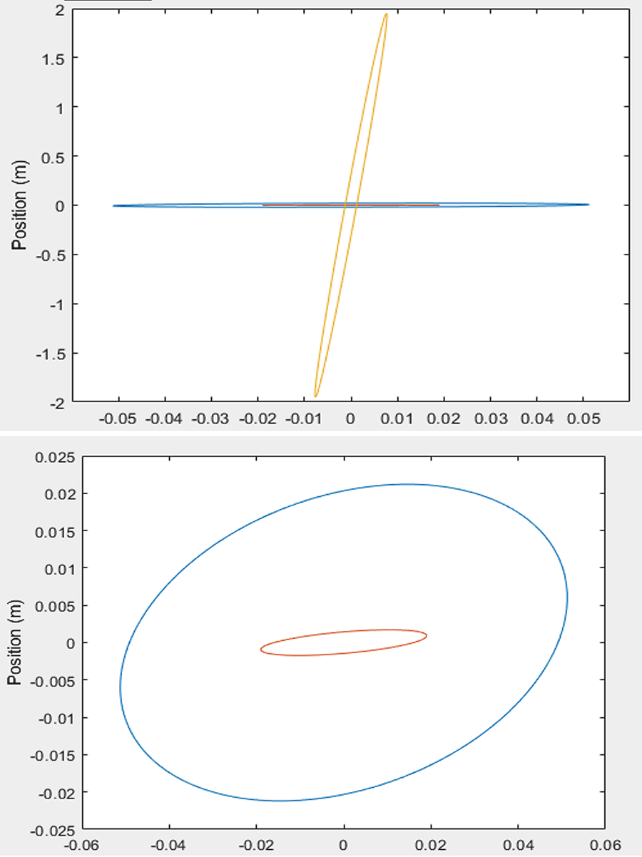
The 95% covariance ellipse of the center of masses, show how the dummy falls if not sustained by the walker (Figure 2A, orange). Note that the axes of the figure have different scales, to show that the excursion in the direction of the fall is almost 2 meters, while in the orthogonal direction the movement of the center of mass is less than 5 cm. The covariance of both the dummy and the walker when the user is supported are shown on the same graph for comparison, and separately in Figure 2B. The center of mass of a dummy in free fall immediately falls to the ground, in a span of 1.2 seconds. It should be noted that the time it takes the average person to fall is 2.4 seconds [21]. Thus, it shows that the stiffness values chosen in the dummy, especially in the ankle and hip, lead to the person being twice as quick to fall. If the walker-wheelchair can remain stable with this dummy, it likely can in a variety of circumstances with most if not all possible individuals, as we have simulated a most extreme case. Our simulation using the calculated stiffness values of the joints and rubber bands shows that the walker does not tip over when a user begins to fall, and furthermore prevents the fall from completing. Figures 2B shows that the center of mass of the walker moves much less than that of the dummy (i.e. it will not topple) and also shows that the center of gravity of the dummy sway of less than 5 cm showing that the walker greatly increases the person's stability.
DISCUSSION
There is a need for a walker with built-in wheelchair, which is low-cost and outdoor capable, as well as offering torso support and sit-to-stand assistance. A device that people in any area of the world could use long-term, since its designed with resources available in almost every resourced and low resource area. This study shows such a device design performs well at its function of supporting a person's weight to aid in the process of walking. Current simulation and development work in progress will eventually lead to the ability to perform standardized tests to assure the device meets industry standards. This design achieves several needs not currently found combined into one product.
REFERENCES
- Kaye HS, Kang T, LaPlante MP. Mobility device use in the United States: National Institute on Disability and Rehabilitation Research, US Department …; 2000.
- Dodd KJ, Taylor NF, Damiano DL. A systematic review of the effectiveness of strength-training programs for people with cerebral palsy. Archives of physical medicine and rehabilitation. 2002;83(8):1157-64.
- Bhadelia N. Rage Against The Busted Medical Machines. 2016.
- Sharan D, Rajkumar JS, Balakrishnan R, Kulkarni A, Selvakumar K, Gampa S, et al. Effectiveness of a low-cost body weight support training device in the rehabilitation of cerebral palsy. Journal of rehabilitation and assistive technologies engineering. 2016;3:2055668316676047.
- Rigid Lifelines S, INC. Maximum Arresting Force. 2021.
- Thera-Band Colors Sequence Resistance Levels: prohealthcareproducts.com; 2021 [cited 2021]. Available from: https://www.prohealthcareproducts.com/blog/theraband-colors-sequence-resistance-levels/.
- Dressel A, Sadauckas J. Characterization and modelling of various sized mountain bike tires and the effects of tire tread knobs and inflation pressure. Applied Sciences. 2020;10(9):3156.
- Pasco. Bicycle Wheel Mass Set. 2021.
- Physics F. (1 of 2) Measuring the Rotational Inertia of a Bike Wheel. 2018.
- Stinson K, Roberts C, Gray B, Rhodes E, Fleming E, Martin G, et al., editors. Coefficient of friction between tires and road surfaces. Highway Research Board Proceedings; 1934: National Research Council (USA), Highway Research Board.
- Van der Woude L, Van Konlngsbruggen C, Kroes A, Kingma I. Effect of push handle height on net moments and forces on the musculoskeletal system during standardized wheelchair pushing tasks. Prosthetics and Orthotics International. 1995;19(3):188-201.
- Bartel DL, Davy DT. Orthopaedic biomechanics: mechanics and design in musculoskeletal systems: Prentice Hall; 2006.
- Bae J-J, Kang N. Development of a five-degree-of-freedom seated human model and parametric studies for its vibrational characteristics. Shock and Vibration. 2018;2018.
- Giles JW, Boons HW, Ferreira LM, Johnson JA, Athwal GS. The effect of the conjoined tendon of the short head of the biceps and coracobrachialis on shoulder stability and kinematics during in-vitro simulation. Journal of biomechanics. 2011;44(6):1192-5.
- McQuade K, Price R, Liu N, Ciol MA. Objective assessment of joint stiffness: a clinically oriented hardware and software device with an application to the shoulder joint. Journal of novel physiotherapies. 2012;2(7).
- Celik H, Chauhan A, Flores-Hernandez C, Dorthe E, Goodine T, D'Lima D, et al. Vertical and rotational stiffness of coracoclavicular ligament reconstruction: a biomechanical study of 3 different techniques. Arthroscopy: The Journal of Arthroscopic & Related Surgery. 2020;36(5):1264-70.
- Ingram LA, Snodgrass SJ, Rivett DA. Comparison of cervical spine stiffness in individuals with chronic nonspecific neck pain and asymptomatic individuals. journal of orthopaedic & sports physical therapy. 2015;45(3):162-9.
- de Bruijn E, Van der Helm F, Happee R. Analysis of isometric cervical strength with a nonlinear musculoskeletal model with 48 degrees of freedom. Multibody System Dynamics. 2016;36(4):339-62.
- Byrne RM, Aiyangar AK, Zhang X. Sensitivity of musculoskeletal model-based lumbar spinal loading estimates to type of kinematic input and passive stiffness properties. Journal of biomechanics. 2020;102:109659.
- Zinder SM, Granata KP, Shultz SJ, Gansneder BM. Ankle bracing and the neuromuscular factors influencing joint stiffness. Journal of Athletic Training. 2009;44(4):363-9.
- Bagala F, Becker C, Cappello A, Chiari L, Aminian K, Hausdorff JM, et al. Evaluation of accelerometer-based fall detection algorithms on real-world falls. PloS one. 2012;7(5):e37062.