Sam Rostami, Sang Hee Kim, Evelyn Novoa, Raniel Calilung
University of California, Irvine, Biomedical Engineering
Background
Floor-to-wheelchair transfers are one of the most difficult transfers for individuals with lower body mobility impairments. With the average wheelchair user requiring 8 non-level transfers per day, floor-to-wheelchair transfers are an essential part of the majority of wheelchair user's daily life [1]. Due to the wheelchair seat height ranging between 17 to 25 inches above the floor, it is a significantly challenging task to achieve a floor-to-chair transfer without exceptional upper body strength or assistance from others.
In order for an individual to independently get back onto their wheelchair after falling, either a forward, sideways, or rear facing floor-to-chair transfer is required. For the vast majority of individuals, however, getting back onto the wheelchair from the ground can result in upper limb pain and injuries such as cuff tears, shoulder and wrist pain, and could potentially cause a permanent or life-threatening injury. Almost half of wheelchair users never acquire the proper practice and methodology behind transfers throughout their rehabilitation period [2].
Once on the floor, most wheelchair users are forced to crawl using their hands which can lead to excruciating wrist pain and skin damage on the back of the hand. With an estimated 75 million individuals lacking wheelchairs in developing countries as well, many individuals are forced to crawl around with shoes on their hands in order to just barely protect their hands from varying elements [3].
Approach
There are currently two categories of products pertaining to non-level transfers: lift sling products and step ladder products. The present lift sling products available in the market are expensive and require an external operator to accomplish a successful transfer. Such devices are also limited to preset and indoor settings due to their general lack of mobility. For individuals with a Functional Independence Measure (FIM) score of 4 or above, however, a floor-to-wheelchair transfer is possible without the use of a lift sling. For such individuals, a household object or an elevated surface is recommended to further assist with such transfers. Step ladder products are currently the only available solution in the market targeted towards independent floor transfers. Such devices, however, are expensive and also lack portability, limiting their availability when a non-level transfer is required.
To learn more about the clinical unmet need, two rounds of voice-of-the-customer interviews were conducted. The first round of interviews was focused towards understanding the clinical unmet needs of individuals who use wheelchairs. One hundred wheelchair users were interviewed with a dynamic range of demographics and lower body impairments including different levels of spinal cord injuries, rheumatoid arthritis, cerebral palsy and multiple sclerosis. Through the conducted interviews, a clear need for a portable and independent device that can increase the maximum achieved hip height was determined.
For the second round of interviews, twenty-seven qualitative solution interviews were conducted with licensed therapists specializing in wheelchair mobility and rehabilitation. The purpose of such interviews was to solidify an approach to creating the ideal device for the end users and early adopters. Device customization was the primary input that was received through conducted interviews with the therapists. Due to the variation in each person's mobility and upper limb capabilities, the device needs to be either adjustable or customizable to meet the user's preferences.
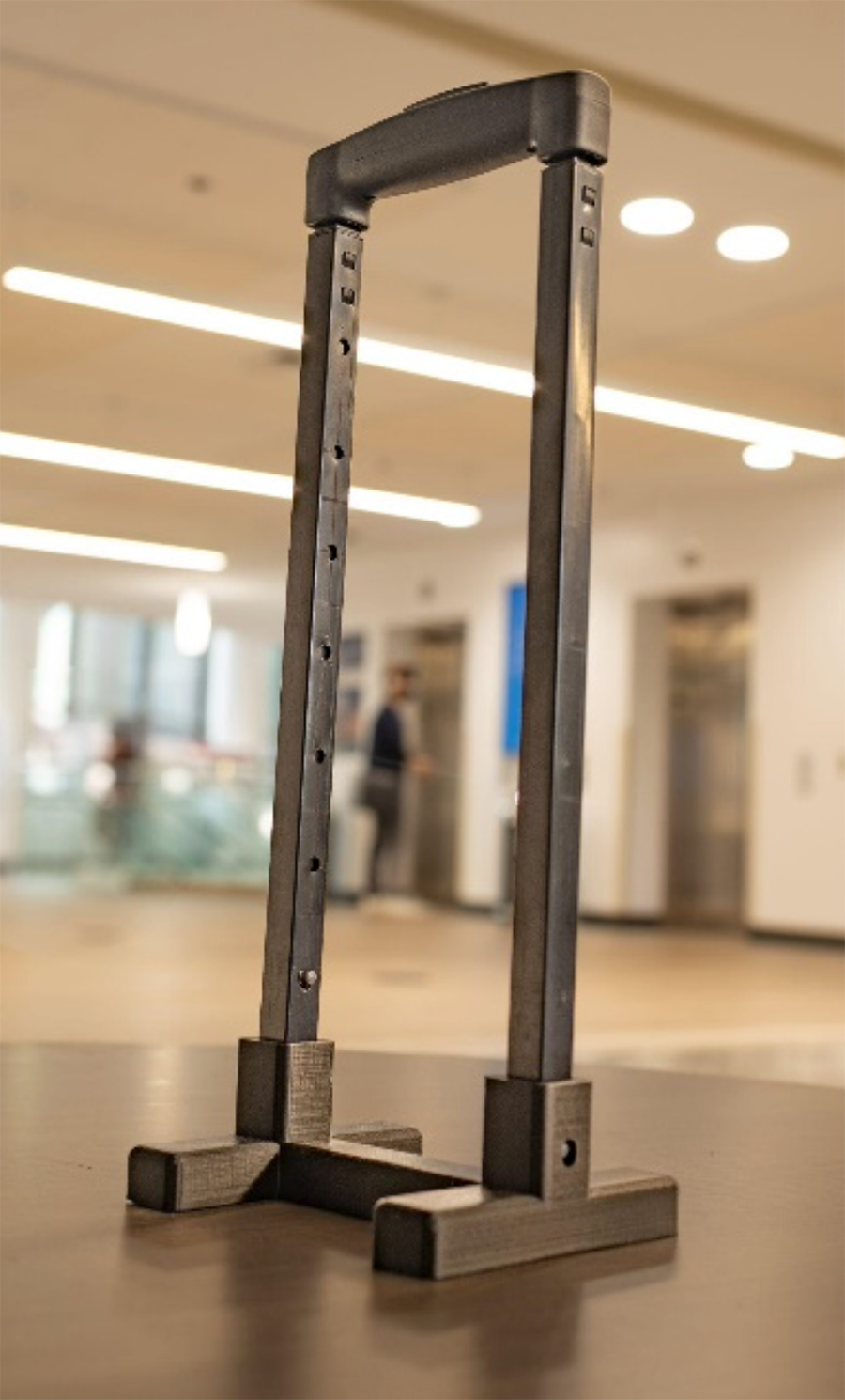
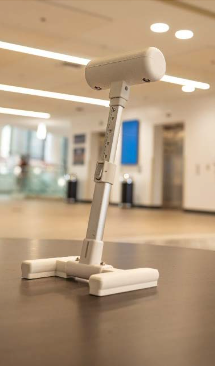
To test device capability, the first iteration of the device consisted of a suitcase handle attached to a solid 3D-printed base, shown in Figure 1. Additional holes were added into the shaft portion of the handle for height adjustability. The second iteration, Figure 2, included similar parts to the initial design, except the handle was changed to a cylindrical bar to allow for a better grasp and distribution of weight while transferring. The second prototype was also successful in regards to functionality; however, it was not compact and portable as previous validation testing deemed it necessary.
The purpose of this study is to create a device that can address the mobility needs of individuals who use wheelchairs in a portable and independent manner. The three categories of design criteria addressed are functionality, durability, and comfort. For functionality, a minimum of 10 in increase in the maximum achieved hip height displacement is required. It is necessary for the device to be portable as well to allow the end user to have access to said device at any given time. To meet the durability requirements, the device must be able to support an excess of 400 lbs., survive extreme temperature and environment settings, and undergo usability testing to analyze behavioral patterns and weight distribution. In regards to comfort, the device must undergo validation testing to determine utility requirements.
Final Design
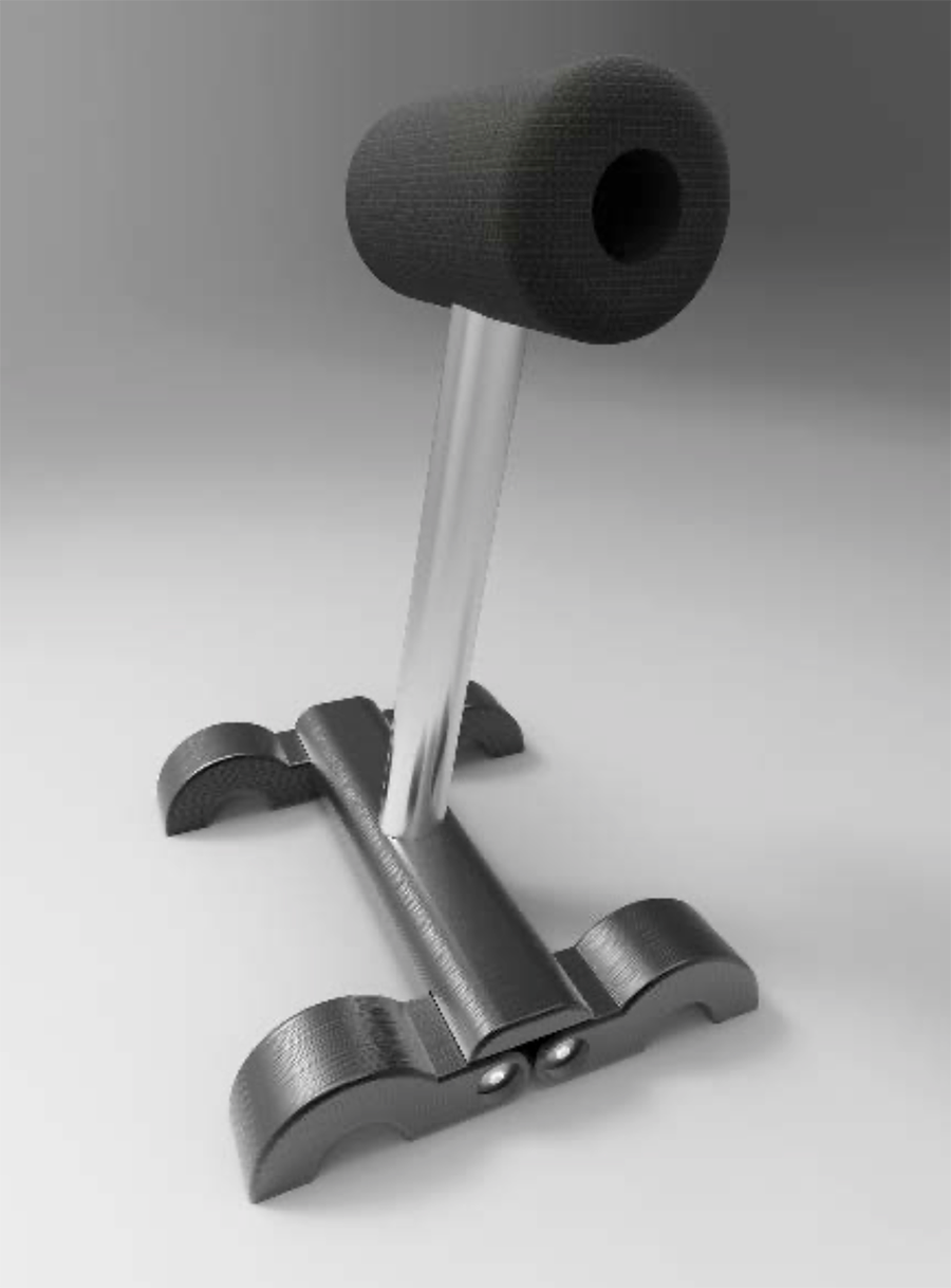
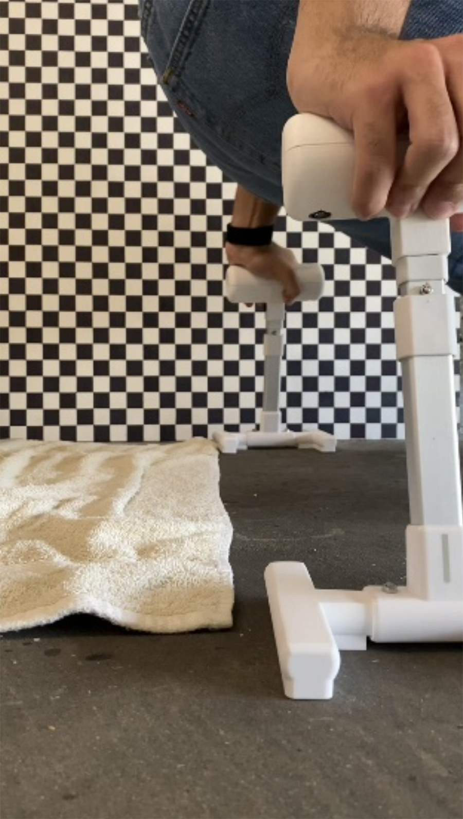
The final iteration of the device, named the Assist Handle, consists of three main parts: a cylindrical handle with a hollow hole in the center, a base with a plurality of foldable opposing legs, and a shaft to attach the handle to the base while assembled. The handle and the base are 3D printed using ABS plastic. The hollow and threaded metallic shaft is made of galvanized steel. The device consists of an assembly mechanism that allows the user to assemble and disassemble the handle in the matter of seconds. To assemble the device, the base is unfolded and taken off of the handle. The shaft is then removed from within the handle and subsequently attached to the handle and base through a threaded connection.
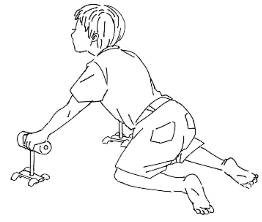
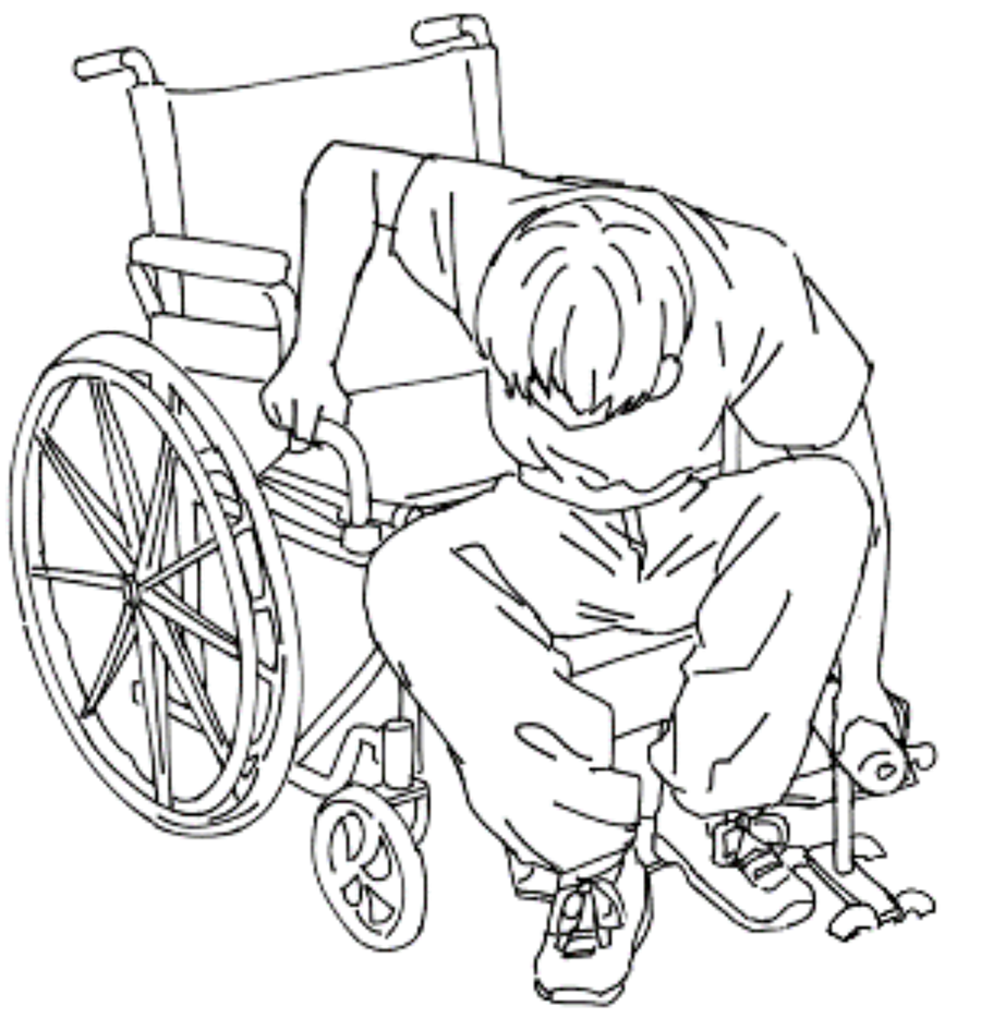
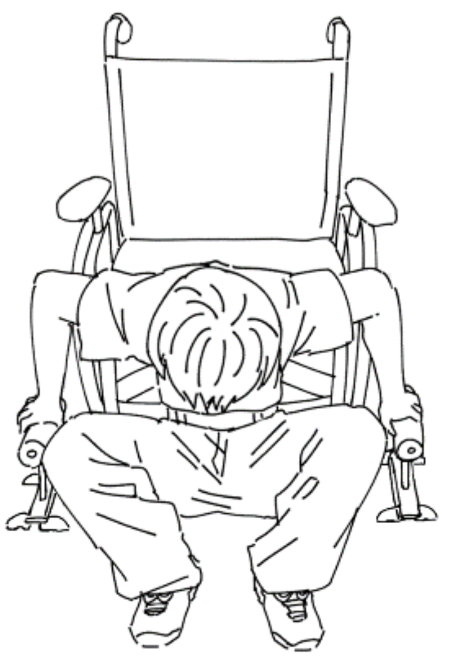
Figure 5B: Rear floor transfer performed with two of the Assist Handles
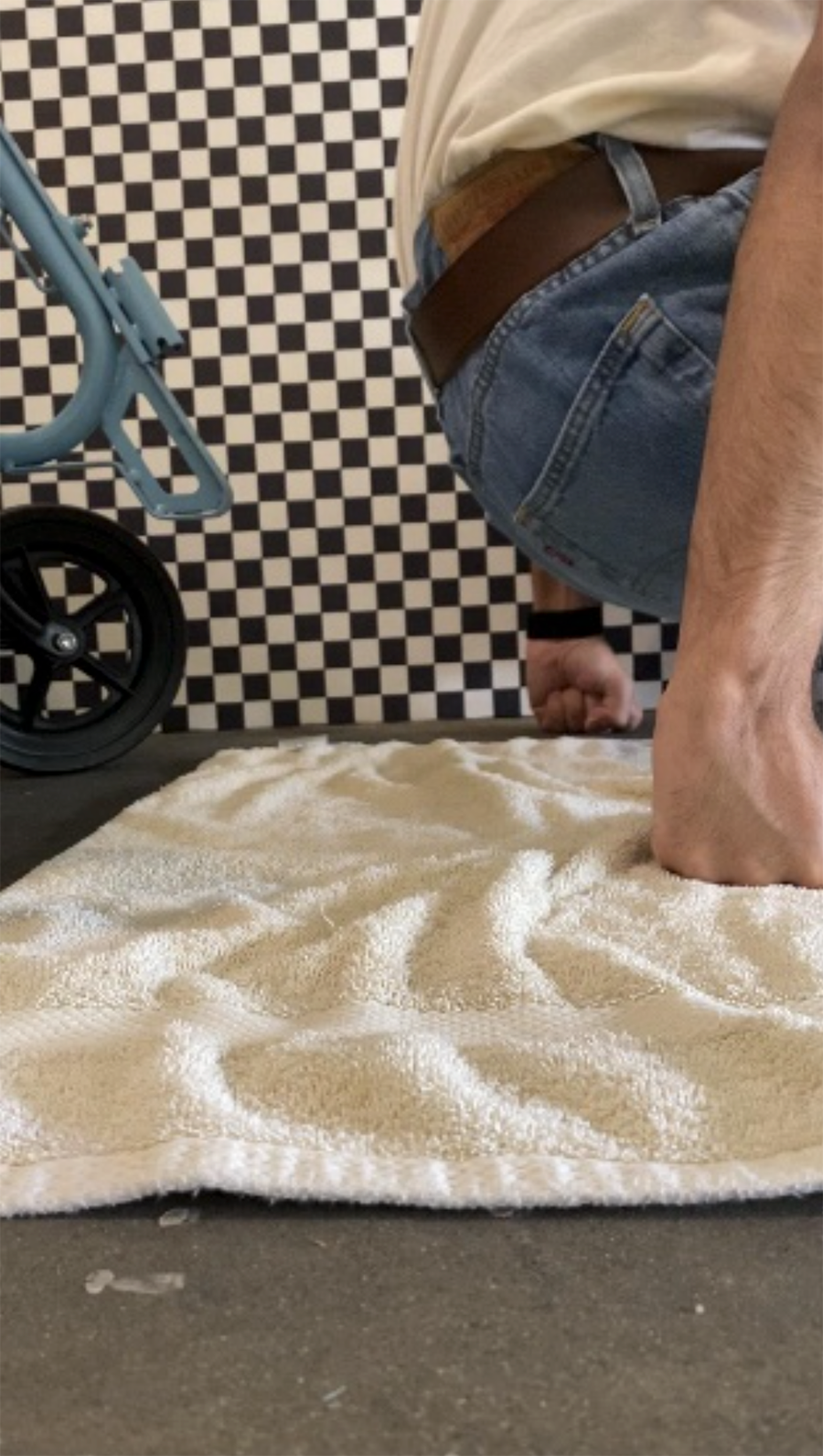
Figure 5C: Two of the Assist Handles used as crawling supports
When assembled, shown in Figure 3, the Assist Handle can be used to help users accomplish a variety of transfers and mobility tasks. In regards to sideways floor transfers (Figure 5A), the end user will place said device on the floor while pushing onto the cylindrical handle and respectively propelling themselves back onto desired elevated surface. For rear floor transfers (Figure 5B), similar steps are required, allowing the individual to use one Assist Handle for each hand if desired. The pair of said devices can also be used as crawling support (Figure 5C) by protecting the user's hand from various elements while crawling on the floor.
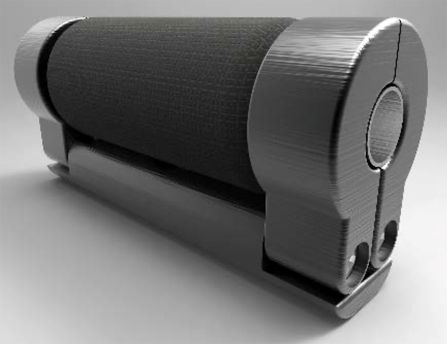
In its disassembled state, shown in Figure 4, the device has a relatively cylindrical shape, allowing for efficient storage while not in use. Through a universal snap fit mechanism as well, the Assist Handle can easily be attached to the side of most manual wheelchairs, making the device easily accessible to the user when necessary.
Usability Testing
To further test the design criteria of the Assist Handle, multiple rounds of usability testing were conducted. Five participants enrolled in the study, all of which had efficient control over quadricep and trunk muscles. Due to the uncontrollable contraction of lower limb and trunk muscles, the collected data is not representative of the targeted population, but rather serves as testing of the general functionality and quality of the device. It is important to note that the usability trials were conducted purely for initial testing purposes. Further testing will be conducted as the safety of the device is established through future rounds of failure analysis.
Displacement Testing
To validate the hypothesized improvement of the mentioned device, displacement testing was performed to compare the maximum hip height achieved with and without the Assist Handle. A 36 by 24-inch grid board consisting of 1-inch squares was placed on the side of the participants to measure displacement. Each trial was recorded using a camera fixed in the same position for consistency throughout the testing procedure. All measurements obtained in the test were scaled accordingly using spatial resolution imagery.
First, each participant was asked to lay on the ground parallel to the grid board, with their legs lying flat on the ground. The participants would then attempt to lift themselves up as high as they can by pushing on their hands and continuously keeping their legs flat, as shown in Figure 6. The same process was repeated a total of 30 times. The second round of the displacement testing required the participants to repeat the same steps as the first, but while using the Assist Handle, shown in Figure 7. The maximum hip displacement for each attempt was recorded using video capturing software. Through the acquired results, the use of the Assist Handle increased the maximum hip height by a mean of 12.5 inches.
Weight Distribution Testing
The weight distribution test was conducted to determine the maximum weight placed onto the participant's upper extremities while transferring. Prior to testing, the accuracy of each digital scale was measured using a 30-pound weight. The percent error of both digital scales was measured at 0.333%. The standing weight of each participant was gathered as well prior to testing.
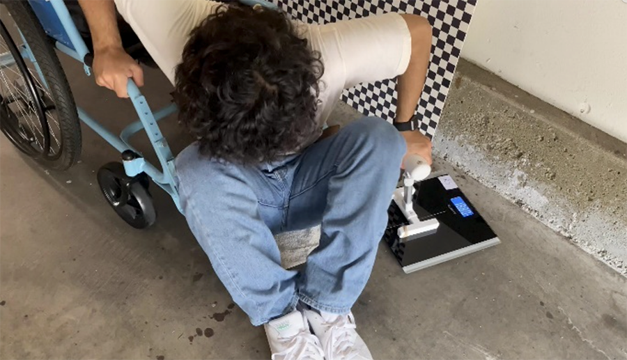
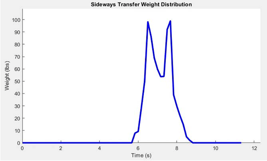
Figure 8B: Graph of sideways transfer weight distribution throughout the transfer duration
The first round of the weight distribution test focused on sideways transfers where each participant pushed onto the scale using their non-dominant hand. Each individual performed 30 sideways transfers without the Assist Handle to act as the control. Following the control sample collection, 30 sideways transfers were performed using the Assist Handle (shown in Figure 8A). The Assist Handle was placed on top of the scale and the values were recorded. Using a Python script, the weight distribution values associated with each attempt were recorded and stored onto a spreadsheet alongside the designated time frame. A MATLAB script was used to graph the collected data, an example of which is shown in Figure 8B. Through the acquired testing, it was determined that a mean of 63.24% of the participant's weight is distributed onto the Assist Handle when side transfers were completed.
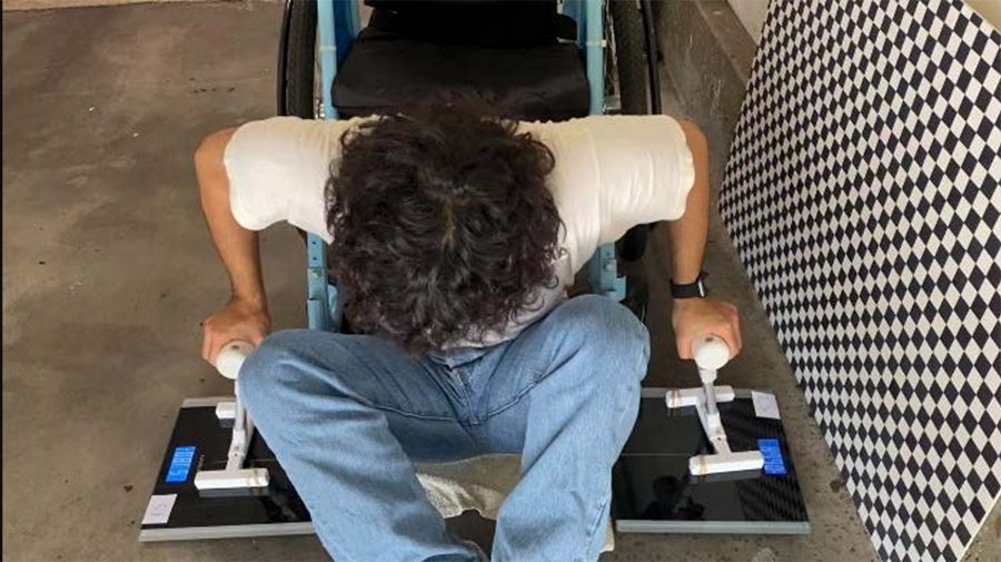
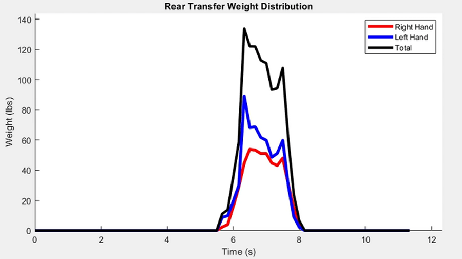
Figure 9B: Graph of Rear Transfer Weight Distribution Throughout the Transfer Duration
The second round of the weight distribution test focused on rear transfers and followed a similar procedure as the first test (shown in Figure 9A). A similar procedure for collecting data was used as well (Figure 9B), where each participant performed 30 transfers with and without two Assist Handles. Due to rear transfers requiring both hands off the wheelchair, there are two scales to measure the weight distributed on each handle. The total distribution of weight was calculated through the summation of the left and right digital scale values. Altogether, the weight distributed is relatively similar to that of the sideways transfer with 63.95% of the body weight on the handles combined.
Cost
To make the initial prototype of the Assist Handle, ABS Plastic was used for the handle, base, and legs. Other components include the galvanized steel shaft to connect the base to the handle using the locking mechanism secured by the M6 screws and M6 nuts. As seen in Table 1, the total cost of manufacturing one Assist Handle is $9.79.
Item |
Cost |
ABS Plastic Handle |
$ 2.70 |
ABS Plastic Base Stem |
$ 2.46 |
ABS Plastic Legs |
$0.42 x 4 = $1.68 |
Galvanized Steel Shaft |
$1.05 |
M6 Screws |
$0.35 x 4 = $1.40 |
M6 Nuts |
$0.08 x 4 = $0.32 |
Epoxy |
$0.18 |
Total |
$ 9.79 |
Significance
The Assist Handle is designed to help individuals using wheelchairs perform floor-to-wheelchair transfers independently without placing extreme stress on their shoulders and wrists. During our usability testing, the Assist Handle was able to significantly reduce the upper limb pain compared to transfers performed without the device.
The Assist Handle will also improve the social aspect of the user by making independent non-level transfers possible. Current existing assistive devices for wheelchairs lack portability or require external assistance, limiting the active space of the individuals' using wheelchairs.
With the Assist Handle, wheelchair users have the ability to leave the house without the concern to ask for help when they fall off a wheelchair.
In developing countries, individuals are lacking access to wheelchairs and are forced to put shoes on their hands to crawl on the ground in order to protect their hands from varying elements. To combat this issue, the Assist Handle can also be used as lowered crutches for crawling support. Holding onto the handle of the device will lower the stress on their arm while protecting their hands from various elements.
References
[1] M. L. Toro, A. M. Koontz, and R. A. Cooper, "The impact of transfer setup on the performance of independent wheelchair transfers," Human Factors: The Journal of the Human Factors and Ergonomics Society, vol. 55, no. 3, pp. 567–580, 2012.
[2] O. Fliess-Douer, Y. C. Vanlandewijck, and L. H. V. Van Der Woude, "Most essential wheeled mobility skills for daily life: An international survey among paralympic wheelchair athletes with Spinal Cord Injury," Archives of Physical Medicine and Rehabilitation, vol. 93, no. 4, pp. 629–635, 2012.
[3] M. Savage, S. Albala, F. Seghers, R. Kattel, C. Liao, M. Chaudron, and N. Afdhila, "Applying market shaping approaches to increase access to assistive technology in low- and middle-income countries," Assistive Technology, vol. 33, no. sup1, pp. 124–135, 2021.
Acknowledgements
We would like to thank our faculty mentor, Dr. Christine King (University of California, Irvine), who provided academic assistance in forming the design criteria and feedback regarding the overall design progress. We would like to thank Dr. Don Schoendorfer (Free Wheelchair Mission), who guided us in regards to the regulatory and monetary requirements for manufacturing and distributing our device in developing countries. We would also like to thank the physical and occupational therapist that we interviewed for offering constructive criticism on the design of the device and conveying other unmet needs that were not previously addressed.