Dinal Andreasen, Senior Research Engineer, Georgia Tech Research Institute, Atlanta Georgia 30332
ABSTRACT
This paper describes an embedded microcontroller-based EMG switch. The controller utilizes real time signal processing algorithms to detect volitional activation commands that will be used to control a single switch. Surface EMG signals are filtered and switch activation logic is based on user selectable features. The switch can be used in situations where the user has minimal muscle control but residual motor activation remains. A USB interface is provided to configure the Flash RAM in the microcontroller allowing access to feature settings. The device may find use as an access device for computer control, environmental control, and as a backup alarm and signaling device.
KEYWORDS
EMG Access Device, EMG Switch.
BACKGROUND
Computer and environmental control access methods for individuals with disabilities include switches based on physical movement, eye movements (eye gaze systems), electroencephalograph (EEG), and electromyograph (EMG). Each system has advantages and disadvantages. There are several advantages to using and EMG based switch. One advantage is the system can sense weak motor command signals even in cases where motor commands are unable to move a limb against gravity. Another advantage is that once an activation site has been identified, the sensor can be attached directly to the skin, and body movements do not disturb the alignment. Switches based on physical movement and eye movement are extremely sensitive to position, and slight movement of the sensor with respect to the user can result in unacceptable operation. Proposed methods to exploit surface EMG signals for human computer interaction have been described (1,2,3). These methods have been based around a personal computer performing such functions as signal filtering, feature extraction, and event classification. This paper describes development of an EMG based single switch based on a mixed signal microprocessor. Recent improvements in microprocessor technology allow sophisticated signal processing algorithms to be implemented with low power, low cost components.
PROBLEM STATEMENT
 |
|---|
The challenge in the design of an EMG based switch is to reliably convert a surface EMG signal to an activation signal. EMG signals are a sum of individual motor neuron firings, and are often contaminated by interference. The waveform measured at the surface is erratic by nature, but signal processing methods can be used to extract the activation signal from the noise. The first part of the problem is concerned with the classification of the recorded EMG signal into an activation state. Determining when the EMG signal exceeds a threshold does not resolve additional issues which may limit the utility of an EMG based switch. The second part of the problem is concerned with adapting to different individuals with unique signal characteristics, and with specialized applications of the switch. Day to day alignment, portability, power supply management, and operation 24/7 require additional features which can be effectively implemented with a microprocessor based design.
METHODOLOGY
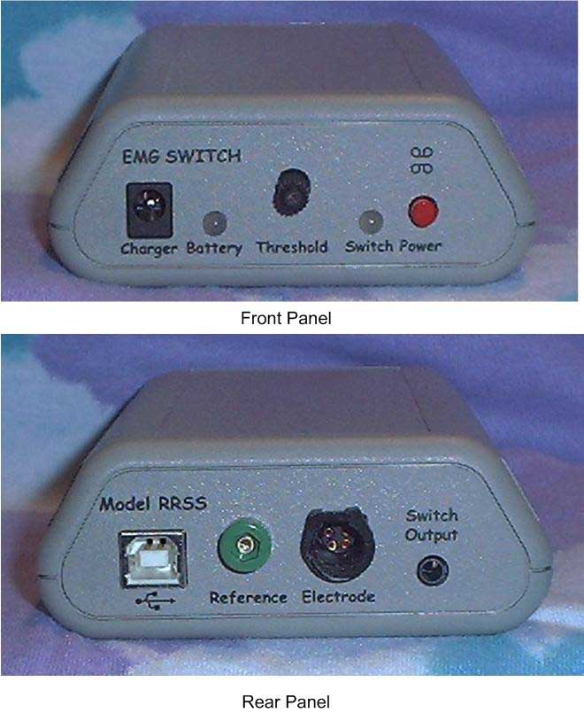 |
Figure 1 shows a block diagram of the EMG based switch, and Figure 2 shows a photo of the front panel of the device. Elements of the system include an active electrode to make contact with the skin and provide an amplified EMG signal. For this system the DE2-3 signal conditioning electrode from Delsys has been employed. The output of the active electrode is coupled to an analog-to-digital converter built into the microprocessor. The signal is sampled at a 1 kSPS rate. The output of the a/d is passed through a digital signal processor. The first stage of the signal processor is a notch filter to minimize hum. The notch filter is a 2 nd order digital filter using a set of difference equations. The output of the notch filter is passed through a rectifier function and then an integrator. The integrator operates over a 50 sample evaluation interval and is reset to zero for the next evaluation period.
 |
Typical waveforms from data recorded from the forehead are shown in Figure 3. For this recording, the user was asked to activate at a one click per second rate, by lifting the eyebrows. The electrode was placed near the center of the forehead and held in place with an adhesive strip provided by the electrode manufacturer. The top trace is the EMG signal from the active electrode. The second trace is the signal after filtering and rectification. The third trace is the 50 sample integration of the rectified signal.
Timing details of the switch activation logic are shown in Figure 4. This figure shows two user programmable parameters: Minimum On Time and Tailbite Time. The Minimum On Time enables the switch for at least the amount of time set by this parameter. When the integrated EMG signal exceeds the front panel threshold setting the switch closure relay is energized and a switch closure is activated. Each time the integrated signal exceeds the threshold, a timer is reset and the switch is forced to remain closed for an additional amount of time set by the Minimum On Time parameter. The figure shows the case of Minimum On Time set to 150 ms. In cases when the timer counts down and the threshold is not exceeded, the switch closure is deactivated. When the deactivation occurs a “tailbite” timer is started. The tailbite timer prevents new activation until it has timed out. The use of these parameters allows a long activation, and helps minimize double switch closures when only one is intended.
 |
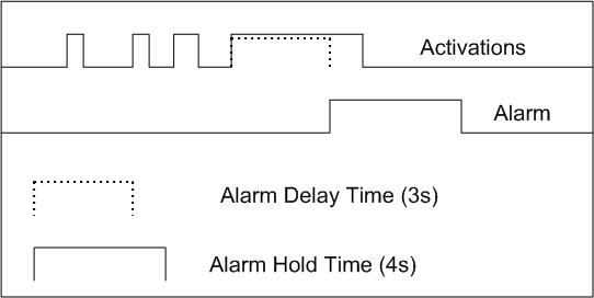
There are several features that can be configured to control the result of activation. One of the intended uses of the device is to act as an audible alarm to signal a caregiver. Either the built in audible piezo transducer can be selected as the alarm device and/or the switch closure relay can be selected. In many cases it is helpful to require an extended activation to trigger the audible alarm event. For example: if the user falls asleep, there may be false activations during dreaming, which would cause false alarms. The two timing parameters which control the alarm mode of the device are shown in Figure 5. The Alarm Delay Time determines the minimum amount of time that activation must be held on for an alarm to occur. The Alarm Time is the amount of time that the alarm remains activated.
 |
There are also several mode selections for the alarm which can be configured over the USB. The alarm can be disabled, it can be triggered by the EMG signal as described above, it can be triggered by a low battery, and it can be set to latch on (i.e the alarm timer never times out and must be reset by a caregiver).
CONCLUSION
Ten of the devices have been fabricated and are undergoing long term Beta testing by interested users. Three ALS patients have been using the device for periods from 4 to 8 months. Two of the patients use the device as a switch input for a speech generating device. The third is using the device as an alarm at night. User comments and suggestions are being incorporated into the microcontroller algorithms and the circuit board layout. Future work will include development of additional features to optimize the utility of the devices in standalone and single switch applications. Development of additional caregiver tools to assist with initial alignment and electrode site location and optimization will be pursued. Algorithms which make use of the analog nature of the signal allowing multiple states from a single site are also being investigated.
ACKNOWLEDGEMENT
The author would like to acknowledge the assistance provided by staff members of Neural Signals Inc, Emerge Medical, and Shepherd Center for their suggestions and encouragement towards the development of this device.
REFERENCES
- Barreto, Armando B., Scargle, Scott D., and Adjouadi, Malek, “A Practical EMG-based Human-Computer Interface for Users with Motor Disabilities” Journal of Rehabilitation Research and Development Vol 37 No. 1, January/February 2000
- Ying-Horng Tarng; Gwo-Ching Chang; Jin-Shin Lai; Te-Son Kuo; “Design of the Human/Computer Interface for Human with Disability – using Myoelectric Signal Control” Engineering in Medicine and Biology society, 1997. Proceedings of the 19th Annual International Conference of the IEEE , Volume: 5 , 30 Oct.-2 Nov. 1997
- Inhyuk Moon; Myoungjoon Lee; Museong Mun;, “A Novel EMG-based Human-Computer Interface for Persons with Disability” Mechatronics, 2004. ICM '04. Proceedings of the IEEE International Conference on , June 3-5, 2004
Author Contact Information
Dinal Andreasen, MSEE,
Georgia Tech Research Institute,
Atlanta, Georgia 30332
(770) 528-7550
dinal.andreasen@gtri.gatech.edu