Alex J. Bevly III, BSE; Donald M. Spaeth, ATP, PhD; Rory A. Cooper, PhD
Human Engineering Research Laboratories, Pittsburgh VA Healthcare System, University of Pittsburgh
Pittsburgh PA
ABSTRACT
Monitoring head position in persons with a traumatic brain injury can potentially provide a means for independent powered mobility. Given the often limited residual functions of attending, visual processing, and motor control, driving an electric-powered wheelchair often depends on supervision to ensure safety. The solution proposed for this problem is to track head position to determine whether the user looks in the same direction they are driving. Head tracking can be achieved by sensing a magnet on the rear of the user’s head with linear analog Hall effect sensors enclosed in a headrest. A specialized interface compares the head position to the direction asserted on a joystick and only permits the chair to move if they are congruent.
KEYWORDS
Traumatic brain injury, electric-powered wheelchair, assistive technology, cuing.
BACKGROUND
For many persons with a traumatic brain injury (TBI), the electric-powered wheelchair (EPW) becomes the most viable mobility option with a direction-sensing joystick interface. Some resounding problems for persons sustaining a TBI are tremor in limbs, spasticity, impairment of motor skills, cognition, visual processing, and attentiveness as collectively reported by Keren and Niemeier [ 1, 2]. These residual deficits not only make EPW driving difficult, but dangerous for the person with a TBI. To drive an EPW, the population with a TBI must hone and develop skills for independent operation.
The presence of severe disabilities makes it difficult for persons to return to their “pre-trauma” activities. Keren’s research points out that residual motor control can be improved; however, the evidence of this motor improvement may only manifest after a long period of “comprehensive and integrated rehabilitation” [ 1]. Therefore, an assistive technology (AT) device is proposed to improve EPW driving skills. Clinical studies reviewed by Kirsch concluded that AT “can facilitate functional performance and contribute to learning of specific adaptive skills” [ 3]. The premise of this research is that persons with a TBI can be cued using AT to drive an EPW; thus “relearning” with their remaining motor control to confer major steps toward independent mobility.
METHODOLOGY
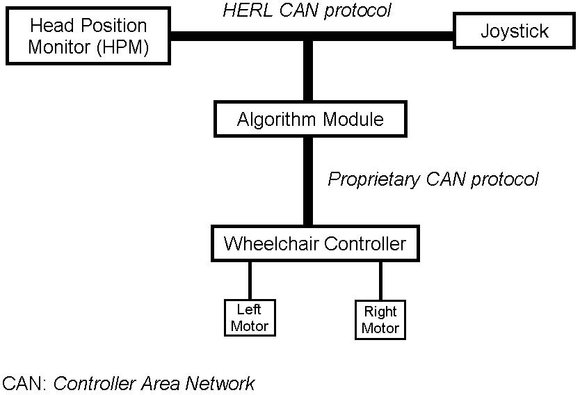 |
The intervention proposed is to inhibit EPW operation until the user aligns their head with the direction asserted by a joystick. This method enforces “cued guidance” when driving an EPW. The proposed approach to assist EPW driving for users with a TBI is the head position monitor (HPM) [ 4], which is integral to the TBI System illustrated in Figure 1 [ 4].
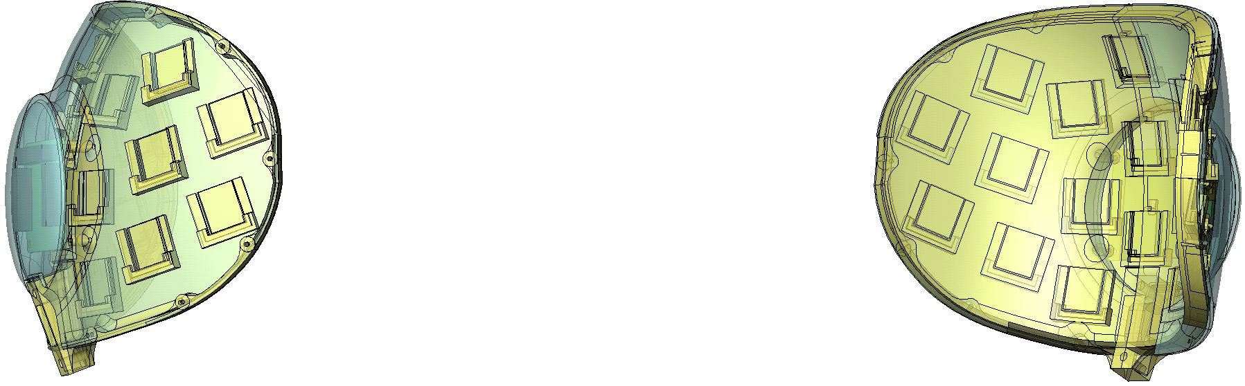 |
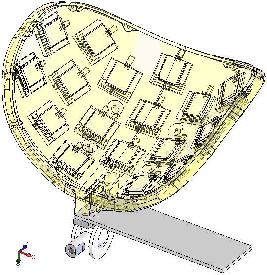
The design of the head position monitor (HPM) incorporates placement of a single magnet on the rear of the person’s head. Then by using an array of strategically placed linear analog Hall effect sensors [ 5] enclosed in a headrest, the magnet can be tracked using a triangulation subset of these sensors [ 4]. An embedded microcontroller monitors the voltage levels of the Hall sensors and uses a triangulation algorithm to determine the magnet’s position. Two different perspectives of a Solid Works computer-aiding draft (CAD) drawing of the HPM shell are shown in Figure 2, where the pockets around the curve hold printed circuit boards that contain the sensors.
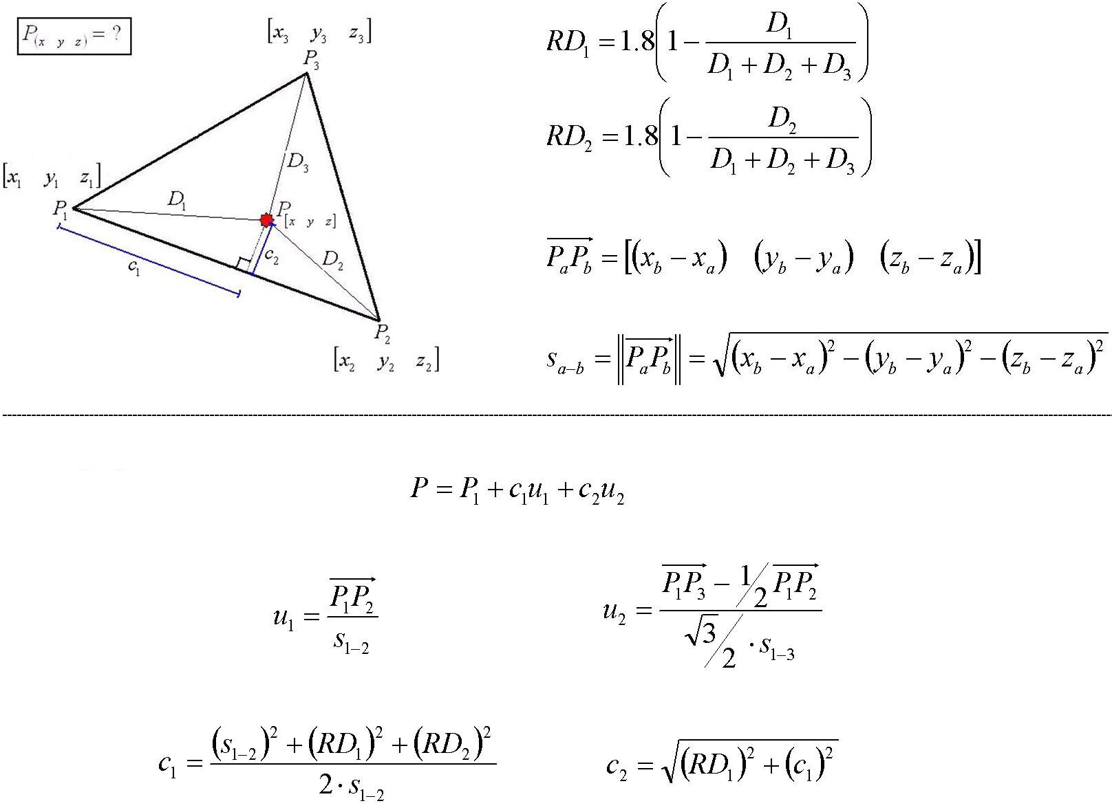 |
When tracking the position of the magnet, the exact coordinates are known for the sensors of the HPM shell. A subset of three sensors chosen forms an equilateral triangle. The HPM algorithm selects the three sensors with the strongest signals to use linear algebra in determining the three-dimensional vector of the magnet position. Figure 3 demonstrates how to solve for the magnet’s position; thus, projecting on the plane of a triangulation subset [ 6]. The vertices of the equilateral triangle are the exact coordinates of given sensors, and the red star corresponds to the unresolved magnet position.
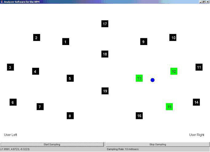 |
To confirm HPM tracking, a two-dimensional Java program was created to display the results on a computer (PC). Serial data from the HPM was fed to the PC where the blue-filled circle in Figure 4 signifies the magnet, while the black squares with white numbers represent the sensors in the HPM shell. Accents of the three surrounding sensors in green indicate that these sensors were selected by the algorithm to plot the magnet position.
CHARACTERIZATION OF ACCURACY
 |
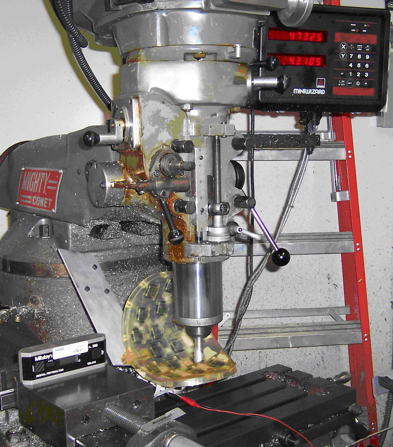
A test procedure was set up with a manual mill to compare the actual magnet coordinates with those reported by the microcontroller. In achieving this, each test point on the HPM needs to be rotated such that it would be orthogonal to the mill’s quill. Figure 5 is a CAD realization detailing a level plate used to measure the angles the HPM was tilted. Figure 6 illustrates the actual HPM angled in the manual mill for a test point.
 |
The magnet was positioned using the mill’s lead screws for each test point, and the calculated position was recorded from the HPM. As a measure of robustness, different angles of tilt for the magnet were considered. A zero (0) degree angle means that the North pole of the magnet is parallel to the test point. The angles tested were zero (0), 30, 45, and 60 degrees.
RESULTS
The average error of the HPM was only 0.1720 inches away from the true position with no deviation angle. This is seen in Table 1, where 33 test points with the associated error of the HPM are shown. Note that magnet deviations greater than 30 degrees were shown to significantly increase the error of the HPM.
| Test Point | Test X | Test Z | Measured X | Measured Z | Distance from Test (average = 0.1720) |
|---|---|---|---|---|---|
| 1 | 0.3993 |
1.6913 |
0.8449 |
1.6888 |
0.4456 |
| 2 | 1.2284 |
1.4530 |
1.4661 |
1.3920 |
0.2454 |
| 3 | 0.1212 |
1.8897 |
0.0369 |
1.7113 |
0.1973 |
| 4 | 2.3334 |
1.3533 |
2.3598 |
1.4377 |
0.0884 |
| 5 | 1.7650 |
1.4440 |
1.8272 |
1.4634 |
0.0652 |
| 6 | 2.4610 |
0.8772 |
2.3042 |
0.7725 |
0.1885 |
| 7 | 3.1762 |
0.7655 |
3.2271 |
0.8044 |
0.0641 |
| 8 | 3.5786 |
0.2917 |
3.6582 |
0.2720 |
0.0820 |
| 9 | 3.4414 |
0.2191 |
3.2825 |
0.2475 |
0.1614 |
| 10 | 2.3160 |
0.0637 |
2.7737 |
-0.0757 |
0.4785 |
| 11 | 1.9755 |
0.6266 |
1.7842 |
0.8403 |
0.2868 |
| 12 | 1.7481 |
0.7954 |
1.8831 |
0.8956 |
0.1681 |
| 13 | 0.9191 |
0.6022 |
0.7705 |
1.6982 |
0.1769 |
| 14 | 1.0704 |
0.5231 |
0.9003 |
0.3504 |
0.2424 |
| 15 | 1.2346 |
1.2862 |
1.2725 |
1.3399 |
0.0657 |
| 16 | 1.0245 |
-0.0690 |
1.0508 |
0.0522 |
0.1240 |
| 17 | 1.3134 |
-0.2644 |
1.3283 |
-0.1572 |
0.1082 |
| 18 | 0.1122 |
-0.1587 |
0.0275 |
-0.2059 |
0.0970 |
| 19 | 0.7736 |
-1.0783 |
0.8842 |
-0.9119 |
0.1998 |
| 20 | 1.1468 |
-1.7150 |
0.9511 |
-1.6742 |
0.1999 |
| 21 | 1.0989 |
-1.4446 |
1.0245 |
-1.5460 |
0.1258 |
| 22 | 1.7031 |
-1.2991 |
1.7834 |
-1.1497 |
0.1696 |
| 23 | 1.4803 |
-0.3754 |
1.6734 |
-0.3700 |
0.1932 |
| 24 | 1.5382 |
-1.0171 |
1.6837 |
-0.9202 |
0.4456 |
| 25 | 2.5184 |
-0.1141 |
2.5998 |
-0.2830 |
0.2454 |
| 26 | 2.4827 |
-0.3924 |
2.2887 |
-0.2079 |
0.1973 |
| 27 | 1.9628 |
-0.2610 |
1.9170 |
-0.2898 |
0.0884 |
| 28 | 2.6957 |
-1.3476 |
2.7616 |
-1.3262 |
0.0652 |
| 29 | 2.9665 |
-0.8218 |
2.8204 |
-0.9386 |
0.1885 |
| 30 | 3.1765 |
-0.8023 |
3.1146 |
-0.6081 |
0.0641 |
| 31 | 3.3986 |
-0.4367 |
3.4253 |
-0.5710 |
0.0820 |
| 32 | 3.0096 |
-0.2029 |
3.1388 |
-0.1308 |
0.1614 |
| 33 | 3.3806 |
-0.7468 |
3.4502 |
-0.7682 |
0.4785 |
DISCUSSION
The HPM physical design specification was to follow the contour movement of the head. Given this condition, it is unlikely for a magnet to deviate more than 30 degrees from parallel to any respective instantaneous point in the shell while in use. Another important HPM characterization is that it is a non-stigmatizing AT. There are no intrusive linkages around the user’s face; only a small magnet on the rear of the head.
CONCLUSIONS
The HPM is sufficiently accurate to proceed with subject trials. Furthermore, the tests conducted demonstrate sufficient accuracy to track head orientation. Use of the HPM in the TBI System can potentially provide persistent cued guidance for the user with a TBI. This ensures that the user will be attentive to the direction of travel driven by an EPW.
REFERENCES
- Keren O.; Reznik J.; Groswasser Z.; Combined motor disturbances following severe traumatic brain injury: an integrative long-term treatment approach. [Case Reports. Journal Article] Brain Injury. 15(7):633-8, July 2001.
- Niemeier J, The Lighthouse Strategy: use of a visual imagery technique to treat visual inattention in stroke patients, Brain Injury, vol.12, no. 5, pp. 399-406, 1998.
- Kirsch, Ned L. 1,5; Shenton, Michelle 1; Spirl, Erin 1; Rowan, James 1; Simpson, Rich 2; Schreckenghost, Debra 3; LoPresti, Edmund F. 4, Web-Based Assistive Technology Interventions for Cognitive Impairments After Traumatic Brain Injury: A Selective Review and Two Case Studies. Rehabilitation Psychology. 49(3):200-212, August 2004.
- Alex J. Bevly III, Donald M. Spaeth, Rory A. Cooper; Improving Electric Powered Wheelchair Operation for Patients with Traumatic Brain Injury, 27 th Annual (2004) RESNA Proceedings.
- Melexis Microelectronic Integrated Systems, Retrieved November 16, 2004, from http://www.melexis.com/prodfiles/MLX90215_Rev007.pdf .
- Anton, Howard; Busby, Robert C.; Contemporary Linear Algebra, pp. 3, 16-17.
ACKNOWLEDGEMENTS
This research is supported by a National Institute of Disability Research and Rehabilitation (NIDRR) Traumatic Brain Injury (TBI) Model Systems Grant
Contact Information:
Donald M. Spaeth, PhD
Human Engineering Research Laboratories (151R1)
VA Pittsburgh Healthcare System
7180 Highland Dr.
Pittsburgh PA 15206
(412) 365-4850
spaethd@herlpitt.org