Edmund F. LoPresti1, Jim Osborn2, Thomas Panzarella3, Thomas Panzarella, Jr.3, John Spletzer4
1AT Sciences, Pittsburgh, PA; 2Carnegie Mellon University; Pittsburgh, PA 3Cook Technologies, Green Lane, PA; 4Lehigh University; Bethlehem, PA
ABSTRACT
An Automatic Transport and Retrieval System (ATRS) is under development to automatically guide a power wheelchair to and from a power lift at the rear of a mini-van. The system uses computer vision and mobile robot navigation technologies to safely move the wheelchair between the lift and the driver’s door. This system will allow a wheelchair user to travel independently in a standard passenger vehicle that needs only minor modifications.
KEYWORDS
Transportation safety, smart wheelchair, rehabilitation robotics, computer vision, van lift
BACKGROUND
Private vehicles are the most frequently used form of transportation by wheelchair users, whether the wheelchair user is a driver or passenger [1]. Many wheelchair users remain in their chair while riding in private vehicles despite the safety risks of using a wheelchair as a vehicle seat [2]. The primary alternative is for the wheelchair user to transfer into a standard vehicle seat and stow the wheelchair separately in the vehicle. However, it may be difficult or impossible for a wheelchair user to stow his or her wheelchair independently once he or she has transferred into the vehicle. Many wheelchair users are thus unable to travel independently.
STATEMENT OF PROBLEM
The goal of this development effort is a system that can automatically stow a power wheelchair in a motor vehicle after the wheelchair user has transferred into the motor vehicle seat and retrieve it when the user is ready to leave the vehicle. To realize this concept, the wheelchair must autonomously travel from the side of the motor vehicle to a wheelchair lift, move onto the lift, and be secured on the lift. The process must be reversed when the wheelchair user arrives at his or her destination.
To meet these needs, an Automatic Transport and Retrieval System (ATRS) is under development. This system uses concepts from mobile robotics, smart wheelchairs and computer vision. Smart wheelchairs have been developed to provide navigation assistance and obstacle avoidance features while the user is in the wheelchair [3]. In the field of mobile robotics, computer vision has been used for navigation and guidance [4]. ATRS combines these technologies into a wheelchair with autonomous capabilities.
METHOD
 |
|---|
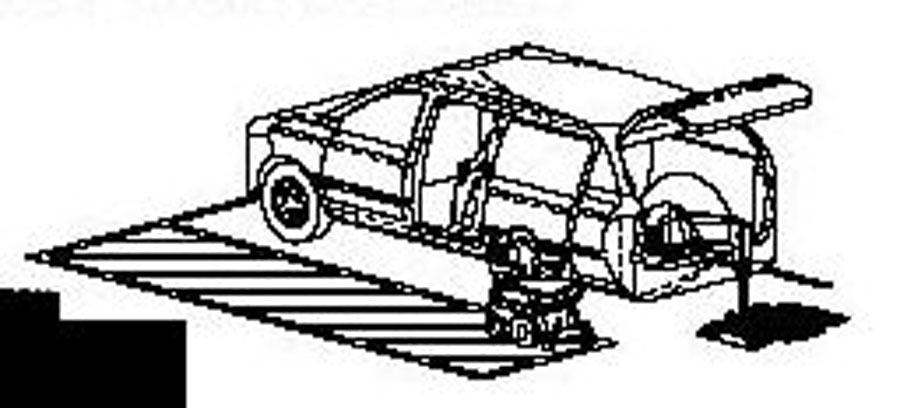 |
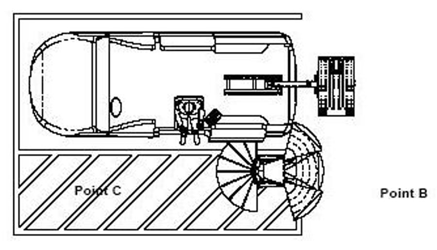
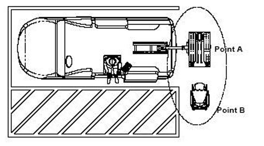
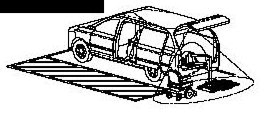
The ATRS employs two sensing modalities to localize the wheelchair’s position relative to the vehicle. The first relies upon range measurements from a laser rangefinder (LRF) for guiding the wheelchair between the location where the user transfers to and from the motor vehicle (Point C, Figure 1) and the vicinity of the wheelchair lift (Point B, Figure 1). The second, based on feedback from a computer vision system, guides the wheelchair on and off the lift (moving from Point B to Point A in Figure 2). Both subsystems run on a computer inside the motor vehicle that remotely controls wheelchair motions.
The wheelchair user first drives the wheelchair to the motor vehicle and transfers into the motor vehicle seat. A control panel inside the motor vehicle is then used to initiate stowing the wheelchair. This control panel also includes a wireless joystick interface allowing the user to take control of the wheelchair if the automated navigation system encounters difficulties. Once the stowing procedure is initiated by the user, the ATRS moves the wheelchair to the rear of the motor vehicle using feedback from a laser rangefinder (LMS200, SICK AG, Düsseldorf, Germany). LRF range measurements are used to not only estimate the relative position of the wheelchair, but also to identify potential obstacles, hazards, etc. In the vicinity of the lift at the rear of the vehicle, the ATRS transfers primary control to the vision subsystem.
 |
|---|
 |
The small tolerances required (on the order of 2 cm in horizontal positioning) for successful docking of the chair mandate a highly accurate estimate of chair pose (position and orientation). This control problem will be addressed with a visual feedback loop used to regulate the wheelchair pose. Similar techniques are often used in manufacturing applications, where a camera is used to position a robot end-effector (e.g. gripper) in proximity to a target/fixture (for grasping, manipulation, etc). For the ATRS, the wheelchair itself corresponds to the end-effector being controlled, and the target is the lift. Varying environmental and lighting conditions will require a robust means for accurately estimating the pose of the wheelchair and lift. To facilitate identifying key features, two-dimensional markers will be affixed to both the lift platform and wheelchair. Localizing the wheelchair and lift in the camera image can then be accomplished by locating the marker patterns, using normalized cross-correlation as a similarity metric. Normalized cross-correlation is robust to changes in scene brightness. Using this in conjunction with high-contrast markers will allow the system to operate properly under varying lighting conditions. Additional image enhancement techniques from machine vision (e.g. histogram equalization) will also be incorporated as necessary for improving tracking robustness.
 |
|---|
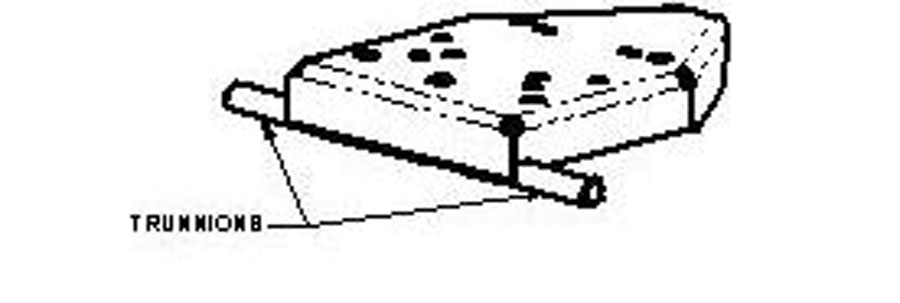
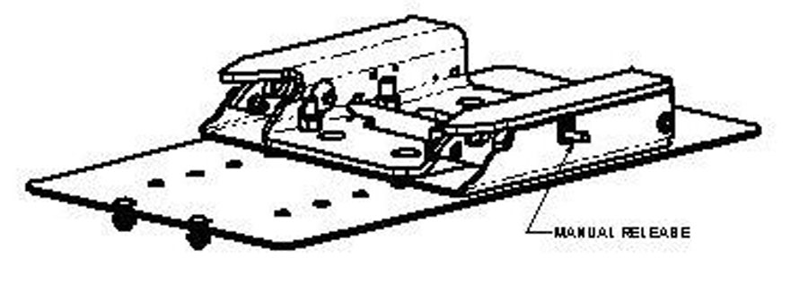
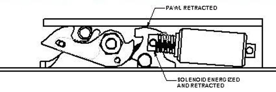
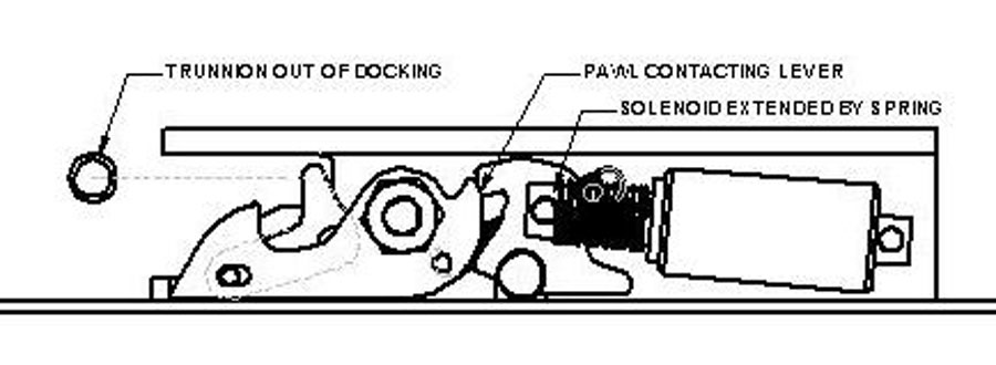
The lift equipped with docking hardware allows the wheelchair to be safely and automatically secured and stowed in the motor vehicle. The docking system consists of a plow bracket affixed to the underside of the wheelchair frame (Figure 3) and a receptacle mounted on the lift (Figure 4). The receptacle has a yoke bracket which connects with the plow bracket on the wheelchair when the wheelchair is moved into position on the lift. The receptacle also includes an electronic solenoid release mechanism, allowing the wheelchair to be locked in place when the plow bracket is in place within the yoke bracket, and unlocked when the user wishes to retrieve the chair (Figure 5).
 |
|---|
Another mechanical component of the system is a motor vehicle seat which simplifies transfer in and out of the motor vehicle. A powered, rearward traversing, turning and lowering seat mechanism will allow the driver’s seat to move backward from the front row to middle row of seats. The seat can then rotate and project outward from the motor vehicle through the rear sliding door. This feature, shown in Figures 1 and 2, will allow the driver to position the motor vehicle seat for ease of transfer to and from the wheelchair. The motor vehicle seat can also be lowered if needed.
 |
|---|
 |
All computations necessary for wheelchair position estimation and control are accomplished by an on-vehicle computer (OVC). Signals from both the wheelchair-mounted sensors and vehicle-mounted camera are transmitted to the OVC. The OVC processes the signals and generates linear and angular wheelchair velocity signals in order to compensate for errors in the chair’s trajectory. The control inputs are then translated into speed and direction signals appropriate to a joystick, and transmitted to a microprocessor on the chair itself. The microprocessor then generates appropriate voltage levels to simulate an attendant joystick. When the ATRS is not in use, this control interface relinquishes control to the wheelchair user’s primary joystick. Transmission of sensor data from the wheelchair to the OVC, and control signals from the OVC to the wheelchair, is accomplished over a wireless communication link.
DISCUSSION
A prototype ATRS system is under development for a particular model of wheelchair (Pronto M91, Invacare, Elyria, OH). This prototype will be used to test the basic technology under ideal conditions (e.g. flat, smooth ground surface; motor vehicle at least 2 meters from neighboring cars; stationary obstacles). This prototype will also be used to elicit feedback from potential users with regard to the perceived value of this system, and desirable features or potential difficulties. Based on this feedback and results of initial testing, future prototypes will be developed which function with a variety of wheelchair models and adapt to a variety of environmental conditions.
REFERENCES
- Rotko, K.A., Songer, T., Fitzgerald, S., Karg, T. (2004). Characteristics of Wheelchair Users and Associated Motor Vehicle Transportation Usage. Proc. RESNA 2004 Annual Conference.
- Bertocci, G, vanRoosmalen, L. (2003). Wheelchair caster loading during frontal motor vehicle impact. Assistive Technology, 15:105-112
- Simpson, R., LoPresti, E., Hayashi, S., Nourbakhsh, I., Miller, D. (2004). The Smart Wheelchair Component System. Journal of Rehabilitation Research and Development. 41(3B):429-442.
- Das, A. Fierro, R. Kumar, V. Southall, J. Spletzer, J., Taylor, C. (2001). Real-time vision based control of a nonholonomic mobile robot. IEEE International Conference on Robotics and Automation, pp. 1714-1719.
ACKNOWLEDGMENTS
This Project was financed in part by a grant from the Commonwealth of Pennsylvania, Department of Community and Economic Development. The authors thank Invacare for providing power wheelchairs for use in developing the ATRS prototype.
Author Contact Information:
Edmund LoPresti, Ph.D.
AT Sciences
160 N. Craig St. Suite 117
Pittsburgh, PA 15213
Phone: 412-687-1181
Fax: 412-687-1181
E-mail: edlopresti@at-sciences.com