Upper-Limbs Rehabilitation Devices
Part II - Passive Devices
Oren Masory and Oliver Sanroma
Department of Ocean and Mechanical Engineering, Florida Atlantic University, Boca Raton, FL 33431ABSTRACT
The motivation and design aspects of a passive upper-limb rehabilitation devise are discussed. It consists of three springs that are anchored on one end and attached to a joystick, held by the patient, at the other end. The springs provide resistance as the joystick is being moved. The user is given, in real time, instruction how to move the joystick so that a certain level of resistance is maintained. During the motion the position of the joystick is recorded and the data can be used to determine his recovery progress.
INTRODUCTION
As mentioned in the previous paper, the numbers of individuals who experience Stroke, Multiple Sclerosis, Parkinson’s Disease, Accident Injuries and other causes of neuro-motor dysfunction is increasing. As a result, the number of people undertaking physical rehabilitation is also growing. The increasing costs associated with the needed therapy and the limited time coverage by the insurance companies [1], asks for low cost devices which will allow the patient to perform the therapy at home and thus reduce the cost. Moreover, it will allow to extend the therapy time thereby the therapy will yield better results [2].
The purpose of this paper is to describe a simple passive device for upper-limb rehabilitation. Although it is a passive it provides the following features: 1) Provide load using three springs rather than tension controlled cables; 2) Track the motions of the patient with and without load; 3) Allows the therapist to “program” trajectories and load; and 4) Provide indication related to the patient’s progress.
The device designed to aid both the patient and therapist in maximizing the results of the physical therapy program. With this device, patients are being able to complete at least some of the therapy at home benefiting themselves and over-worked therapists alike [3].
Prior Work
Variety of active devices for upper lip rehabilitation were reported [4 -8] some using articulated robots and some 3 or 4 cable system to manipulate the patient’s upper limp.
The use of planar trajectories is not a problem as most physical therapy motions are on a plane [9,10]. A team headed by researchers at Ohio University investigated planar configurations [11]. They chose to focus most of their investigations and their prototype on the four-cable configuration.
This paper describes a passive rehabilitation system which is based on three springs and an interface that monitors the motion of the patient as well as providing guidance throughout the exercise.
DESIGN OBJECTIVES AND DEVICE LAYOUT
For the devices, described in this paper, to be useful and an improvement over tools and techniques currently available, they should have several necessary characteristics:
- Inexpensive such that it could be used in the home or as a rental
- Flexible in both programming and uses
- User friendly to both the patient and therapist
- To have the ability for remote monitoring to view patient progress as well as the condition of the system itself
- Safe to be operated unsupervised by a patient who is at least competent enough to remain at the device and understand simple operating instructions and commands
The safety of anyone in the vicinity is the most important aspect. This must be maintained at all times, including while the device is unused.
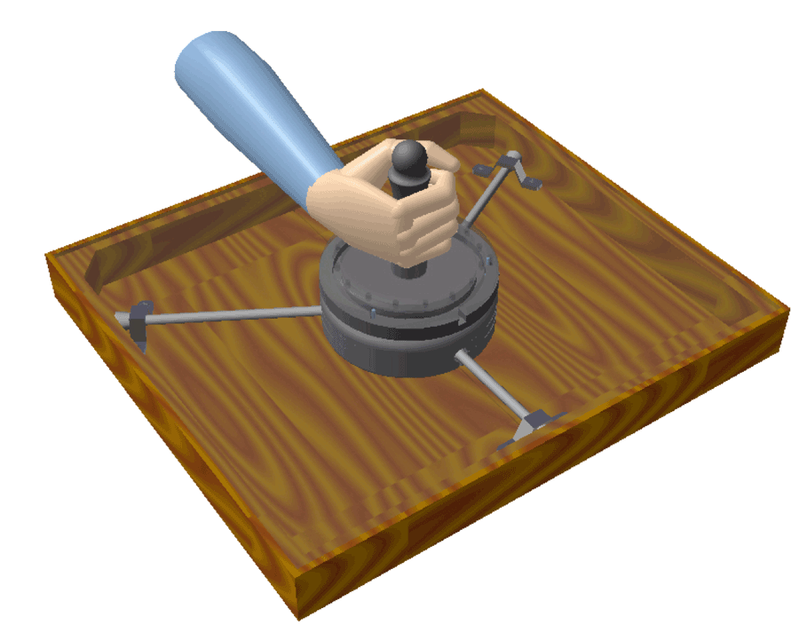 Figure 1: Device outline.
The prototype described here was developed using a tri-spring design. Each spring is anchored to the table at one end and to the end-effector at the other. The end-effector at the end of all the springs has a joystick for the user to hold during operation. The basic outline of the device layout is shown in Figure 1.
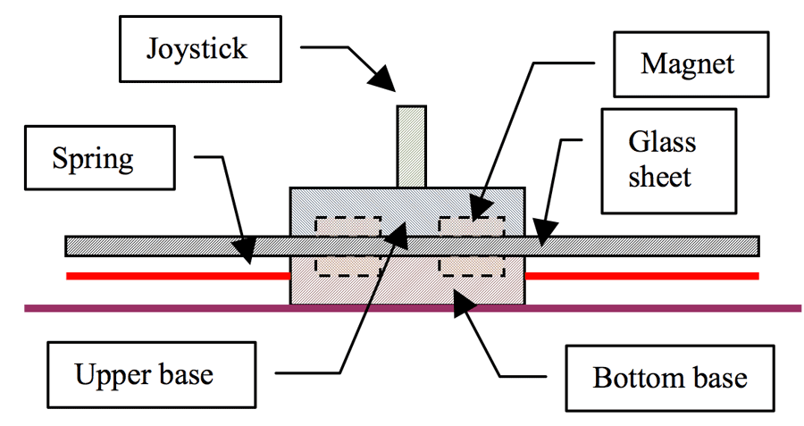 Figure 2: Side-view of the end-effector and joystick mounting
There still is an inherent problem with the possibility that the user’s arm will get entangled in the cables. This is overcome by putting a barrier between the cables and the user, as shown in Figure 2. To allow the user to still “hold” the end-effector and feel the forces applied, the joystick on top of the barrier is magnetically connected to the end-effector platform below the barrier. In this way, the user and the robot can apply forces on each other without a rigid physical connection. This arrangement provides an added safety by the “break-away” of the joystick in case of a malfunction in the manipulator’s motion. The force at which the joystick breaks away can be adjusted through the use of different magnets and distance between the two magnetic platforms.
The upper base is instrumented with 16 LEDs evenly spaced at its perimeter. These LEDs will used to instruct the user in what direction to move. The bottom base is instrumented with a sensor which indicates the position of the joystick on the table.
ANALYSIS
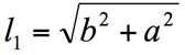
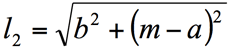
The kinematic layout of the work area is show n in Figure 3. Given the position of the joystick (a,b) the length of each spring can be determine by:
 |
(1) |
|---|---|
 |
(2) |
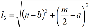 |
(3) |
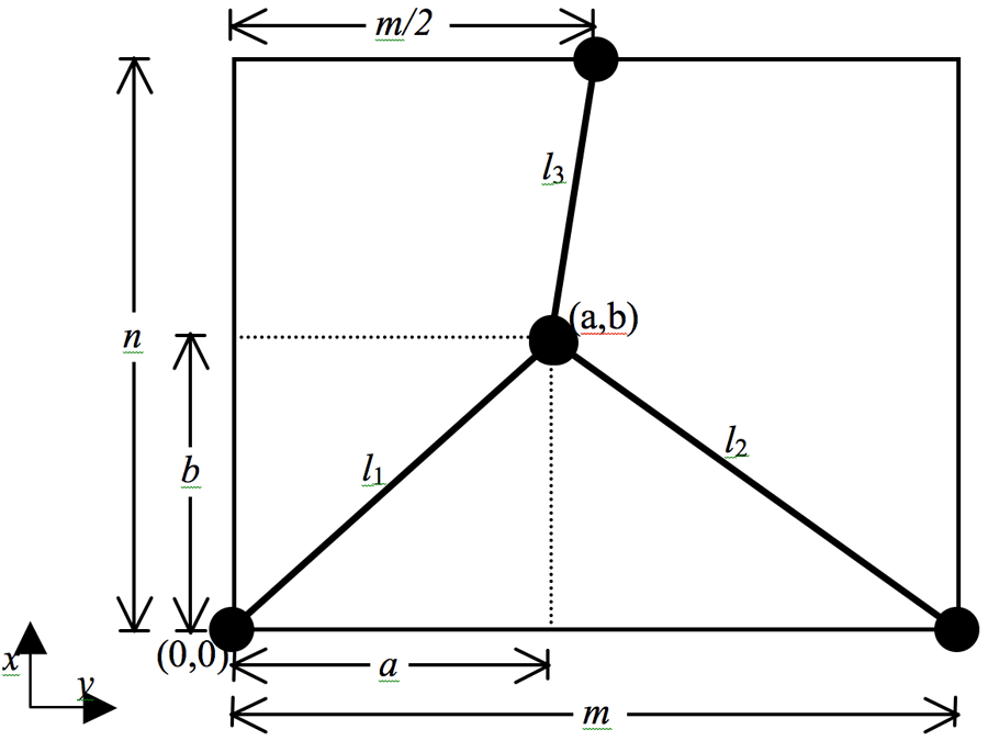 Figure 3: Kinematic layout of the work area
Since the lengths of the unloaded springs are known, the forces applied by the springs, as long as they are in tension, can be calculated:
T![]() i = Ki(l
i = Ki(l![]() i-l
i-l![]() i0)
i0)![]() (4)
(4)
where K![]() i and l
i and l![]() i0 are spring constants and the unloaded lengths of the springs.
i0 are spring constants and the unloaded lengths of the springs.
At any position (see Figure 4) the forces have to be in equilibrium which requires:
T![]() 1+T
1+T![]() 2+T
2+T![]() 3+F = 0
3+F = 0![]() (5)
(5)
where T![]() 1, T
1, T![]() 2 and T
2 and T![]() 3 are the tension in the springs and F is the force applied by the user. Expending Eq. 1 yields:
3 are the tension in the springs and F is the force applied by the user. Expending Eq. 1 yields:
T![]() 1 cos θ
1 cos θ![]() 1 + T
1 + T![]() 2 cos θ
2 cos θ![]() 2 + T
2 + T![]() 3 cos θ
3 cos θ![]() 3 + F cos θ
3 + F cos θ![]() f = 0
f = 0
T![]() 1 sin θ
1 sin θ![]() 1 + T
1 + T![]() 2 sin θ
2 sin θ![]() 2 + T
2 + T![]() 3 sin θ
3 sin θ![]() 3 + F sin θ
3 + F sin θ![]() f = 0
f = 0 ![]() (6)
(6)
where:
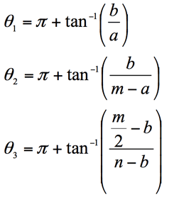
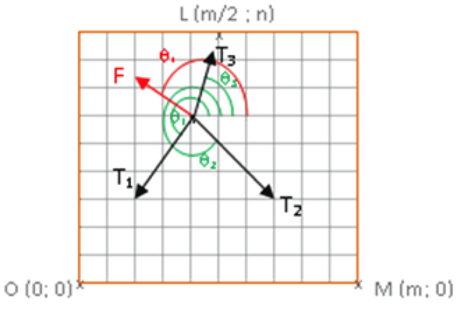 Figure 4: Example of spring tension due to user force
To determine the applicability of the device for rehabilitation purposes it is necessary to map the required force, F, needed for equilibrium, through out the workspace of the device. The magnitude and the direction of this force were calculated on 10 by 10 grid for different spring constants. A sample of the mapping is shown in Figures 5. The different colors correspond to the force’s magnitude and the arrow indicates the direction of the force at the particular grid point.
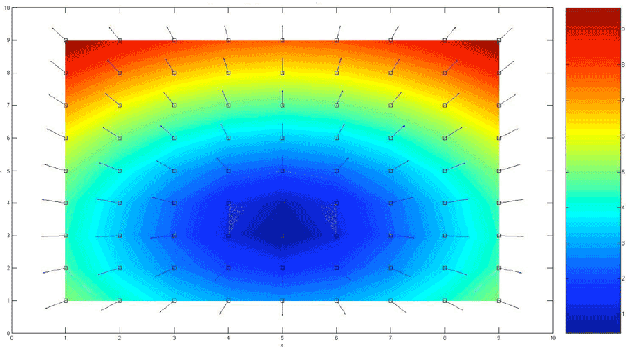 Figure 5: Force field for springs with K=20[N/m].
Once the force field is known a trajectory, possessing a particular characteristics, can be drawn. During treatment the patient, holding the joy stick, will trace the trajectory.
MODES OF OPERATION
Three modes of operation are available:
- Range of motion measurement: In this mode the springs are disconnected and the patient moves the joystick covering the largest workspace he can reach. During the motion the position of the joystick is sampled and displayed on the computer screen.
- Trajectory following: In this mode a trajectory is drawn on the screen and the patient is asked to move the joystick, disconnected from the springs, so that it follows the displayed trajectory. During the motion the position of the joystick is samples and displayed on top of the drawn trajectory. The difference between the references and the actual trajectories are used to evaluate the patient.
- Load application: In this mode, the therapist dictates the magnitude of the load the patient has to apply. Knowing the springs’ constants, the system instructs the patient to move in the direction, indicated by the lit LED, so that the required magnitude of the load is maintained. Figure 6, illustrates the result of such test for a load of 10N using springs with constant of 85[N/m].
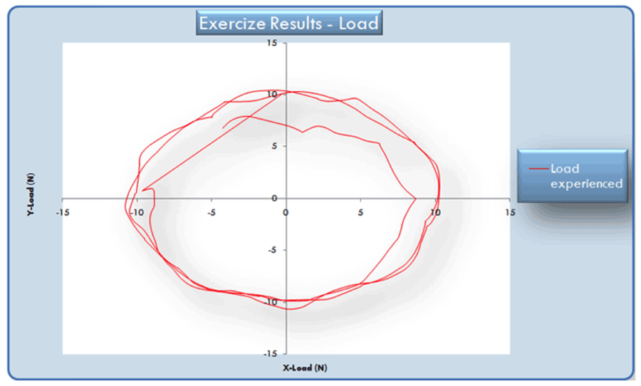 Figure 6: Results for a test with a 10[N] load.
It is important to note that there is no need to solve the inverse problem in order to provide instructions to the user. The system works as follows: At the initial position the end effector is in equilibrium and its position is recorded. Then the user is instructed to move in the Y direction. During the motion the position is sampled and the force is calculated. Once the required force is reached, a search algorithm which determine in which direction to move so that the magnitude of the force will be maintained, is evoked. The algorithm considers the direction of the motion, CW or CCW and the quadrant the joystick is located. Then it determines the magnitude of the force if a small position increment will be taken in the all 7 possible directions and instruct the user, by turning on the appropriate LED, to move in the direction which will maintain the required magnitude as close as possible.
CONCLUSIONS
A simple, low cost passive device for upper limps rehabilitation is presented. Three springs are used to provide resistance as the user is moving his hand along a given trajectory. The system instructs the user to move along a certain trajectory that maintains a constant resistance. The patient’s motion are recorded in real time and can be used for therapy progress evaluation.
REFERENCES
- Bullies, K. “Robot rehab.” Technology Review, 108(9), September 2005, 29-30.
- Reinkensmeyer, D.J., Emken, J.L. and Cramer, S.C. “Robotics, motor learning, and neurologic recovery,” Annual Review of Biomedical Engineering, 6, 2004, 497-525.
- Erlandson, R.F. (1995) “Applications of robotic/mechatronic systems in special education, rehabilitation therapy, and vocational training: A paradigm shift,” IEEE Transactions on Rehabilitation Engineering, 3(1), 1995, 22-34.
- Krebs, H.I., Hogan, N., Aisen, M.L. and Volpe, B.T. “Robot-aided neurorehabilitation,” IEEE Transactions on Rehabilitation Engineering, 6(1), 1998, 75-87.
- Hogan, N. and Krebs, H.I. “Interactive robots for neuro-rehabiliation,” Restorative Neurology and Neuroscience, 22, 2004, 349-358.
- So-Ryeok, O., Mankala, K., Agrawal, S.K. and Albus, J.S. “A Dual-Stage Planar Cable Robot: Dynamic Modeling and Design of a Robust Controller with Positive Inputs” Transactions of the ASME Journal of Mechanical Design, 127, 2005, 612-620.
- Hiller, M., Fang, S., Mielczarek, S., Verhoeven, R. and Franitza D. “Design, analysis and realization of tendon-based parallel manipulators,” Mechanism and Machine Theory, 40, 2004, 429-445.
- Mayhew, D., Bachrach, B., Rymer W.Z. and Beer, R.F. “Development of the MACARM – a novel cable robot for upper limb neurorehabilitation,” Proceedings of the 2005 IEEE 9th International Conference on Rehabilitation Robotics, Chicago, IL, 2005, ThB01-01.
- Johnson, M., Feng, X., Johnson, L. and Winters, J. “Potential of a suite of robot/computer-assisted motivating systems for personalized, home-based, stroke rehabilitation,” Journal of NeuroEngineering and Rehabilitation, 4(6), 2007.
- M. Morris, O. Masory, “A Novel Cable-Driven Robot for Rehabilitation”, Proceedings Israeli Conference or Robotics, Nov. 19-20, 2008, Herzelia, Israel.
- Williams, R.L., II and Gallina, P. “Translational planar cable-direct-driven robots,” Journal of Intelligent and Robotic Systems, 37, 2003, 69-96.
- Morris, M. “A Planar Cable-Driven Robotic Device for Physical Thearapy Assistance” Masters Thesis, Florida Atlantic University, Boca Raton, FL, 2007.
Acknowledgement
The authors wish to express their thanks for Florida Atlantic University support.