DESIGN AND MANUFACTURE OF A WHEELCHAIR TREADMILL
Shuh Jing Benjamin Ying and Stephen Sundarrao
Center of Rehabilitation Engineering and Technology
Department of Mechanical Engineering
University of South Florida
Tampa, Florida 33620-5350
ABSTRACT
A paper presents a design for a low cost wheelchair treadmill with a complete set of instruments to measure torque output and rotating speed of the rollers. The purpose is primarily for use in research studies and is designed for portability by having a reasonable weight using aluminum alloy. The torque transducer is made of a strain gage with an amplifier and a display unit. The rotating speed is measured by a magnetic pickup and indicated by a tachometer. The total duration for this project is about 8 months with some challenges that were encountered due to limited budget and overcome. Details are given in this report. The design also features the ability to elevate one side and provide a gradient as needed.
KEYWORDS
Wheelchair treadmill, wheelchair, treadmill.
INTRODUCTION
The project originated from the School of Physical Therapy at the University of South Florida to design a wheelchair treadmill for research that was to be used in a study of manual wheelchair users. Commercial products did not exist that were applicable. There were a few treadmills used for physical exercise, however these did not provide the instrumentation required. Commercial treadmills are usually equipped with a wide frictional belt (>20”), supported by rollers with tension. The rollers can be powered or without power. The rubber belt can be adjusted to an inclined position for a different exercise. To indicate the effectiveness of the exercise, the indicator often shows how many calories being burned. The parameters were not exactly those needed for the research, although the mechanism was similar to the one planned in the original design.
DESIGN OF MECHANISM
The requirements of the structure is light in weight and rigid in operation with no noticeable deformation. Because of these requirements the materials chosen is aluminum alloy 6061-T6. Structure is built by 3”x 1.5” channel and covered by ¼” plate. The whole size is 112.2” x 36”x 4.25” including a ramp 30” long. The platform can be adjusted to an inclined position by a hydraulic jack with a maximum angle of 4.3o . The rollers in contact with the wheels of wheelchair is designed first to 3.142” in diameter and 33” long, but this diameter is changed to 3” attached with a piece of friction rubber (~ 0.1” thick) to improve the contact property between the wheels and rollers. The shaft of the rollers are1/2” in diameter and are made of steel and supported by self alignment bearings. At one end of the shaft there is a spur gear, 16 pitch 3” diameter. And between these two spur gears, one additional spur gear is installed to make it certain that the rollers are rotating at the same speed. A magnetic pickup for the tachometer is installed beside one spur gear. Because all the spur gears are rotating at the same speed the magnetic pickup can easily sense its speed.
The weight of the whole mechanism is approximately 200 pounds. To facilitate the moving of the apparatus, four handles are installed near four corners. The apparatus is also installed with 6 level mounting devices. When a person with a wheelchair is testing the apparatus, no significant deformation was observed.
To make it certain that the wheels of the wheelchair will be always on the rollers, there are two stops in the front. The position of the stops are adjustable, the distance can be adjusted continuously up to 7 inches.
INSTRUMENTS
There are two instruments in this project: torque meter and tachometer.
Torque meter:
Because of the budget limitation, we can not afford to buy an existing torque meter with magnetic transducer. Instead we developed a torque meter by ourself with a strain gage as a sensor. A strain gage is mounted on a plastic shaft which is chosen for it is easy to produce a large strain with small torque stress. The two terminals of the strain gage are soldered to brass rings and through four brushes to have the strain gage connected to the constant current circuit in the amplifier. The brush mechanisms are parts of a DC motor bought from Grainger, an industrial supply store. The part of the plastic shaft for mounting strain gage is 0.3” in diameter and 1.25” long. The diameter 0.3” is reached through experiment. With this size it is very sensitive to the torque applied. Notice that each DC motor has two brushes, so four brushes are from two motors. Fortunately we can buy the brush mechanisms alone without buying two complete motors. One end of the plastic shaft is connected with the roller of the treadmill the other end of the plastic shaft is connected with a friction controller. Because we must have a load for the strain gage to sense, the friction controller is simply a rotating aluminum drum supported by ball bearings. Without any pressure applied on the surface of the drum, there is little friction to rotate the drum. But there is a piece of plastic arm pivoted at one end and attached to an adjustable screw at the other end, the pressure between the surfaces of rotating drum and plastic arm can be adjusted by a wing nut. With this device the load on the torque sensor can be set to a valve as we want.
Amplifier
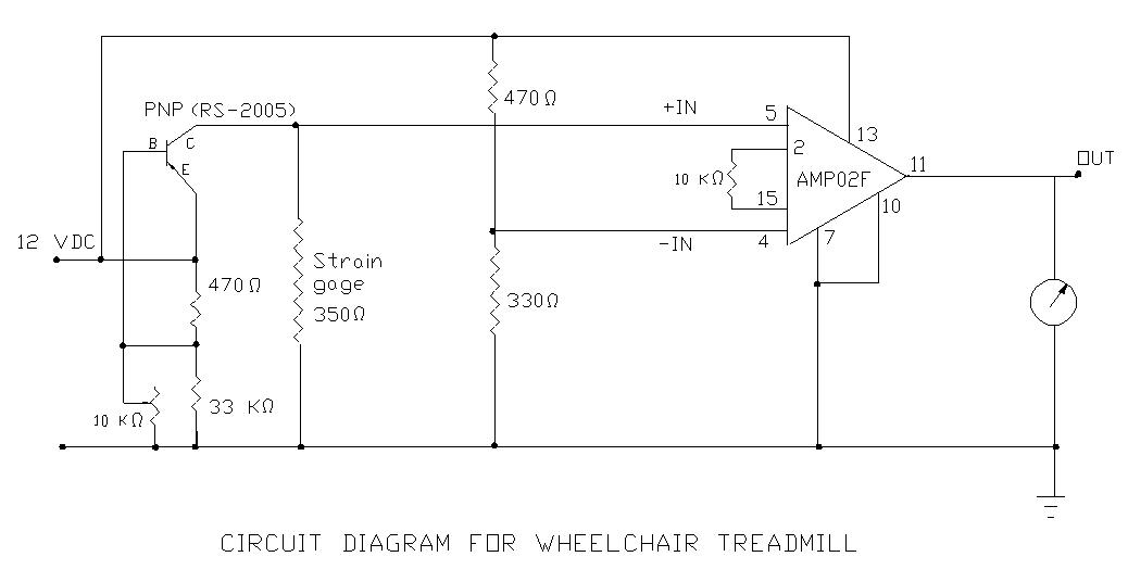 Figure 1. (Click image for larger view)
 Amplifier is consisted of power supply, constant current circuit, signal amplifier and a readout unit. Power supply is simply an ac-dc converter, using 115 vac as input and 12 vdc as output. The constant current circuit is governed by a PNP transistor (RS2005). With the voltage at the base set, the current from emitter to the collector is constant, so that the voltage across the strain will change as the resistance of the strain gage changes because of the changing stress. The current in the strain gage is ~11 mA at the present setting. It can be slightly changed by turning the 10 KW potentiometer. The higher current in the strain gage will make it more sensitive to the stress change but it is limited by its capacity. The output of the strain gage is connected to the (+in) of the amplifier.
The amplifier is obtained from Analog Devices. The one used in the circuit is a 16 pin IC with very small gap between the pins. An adapter is used to let the IC to sit and the 16 pins on the other side can be plugged to a circuit board. The temperature for soldering must be kept no more than 10 seconds at the maximum of 300o C. Therefore a good soldering skill is required for the installation of the amplifier. After the IC is soldered in place the resistor installed between pin 2 and pin 15 must be carefully adjusted because it effects the sensitivity of the amplifier. The value in the circuit diagram 10KW is a nominal value. The readout unit at the output is a voltmeter to indicate the stress in the torque sensor.
The description given above is true only if the strain gage is properly connected in the circuit. Actually the strain gage is mounted on a plastic shaft which is rotating during operation. The wires of the strain gage are attached to brass rings and each ring is equipped with two brushes. The brushes are in contact with brass rings. If this is not an instrument, it may be all right. However this is an instrument and this instrument uses the change of resistance in the strain gage to indicate the stress in the strain gage. The imperfect contact between brushes and rings creates the change in resistance, Consequently, this creates the error in the output. Finally a graphite grease is used to improve the contact property between the brushes and the rings. In addition because there are two brushes on each ring, these brushes are connected in parallel so that the contact property is greatly improved. With all these effort, finally the output reaches a reasonable state and a calibration curve is obtained.
Tachometer
The rotating speed of the rollers is indicated by a panel tachometer (4KF47) which is the readout unit of magnetic sensor (4KF49) by Monach. The magnetic pickup must be mounted by a spur gear. The reading on the tachometer is checked by actual rotating speed of the gear. Calibration curve is obtained.
CONCLUSION
The total cost of this wheelchair treadmill is about $5000.00 without counting my own time. The cost will be doubled if a torque transducer and a readout unit are bought from available market. Because there is no report in the design of wheelchair treadmill found in the literature, this report may be useful to the community looking for a design report for a similar project.
REFERENCES
- Perry, Charles C and Lissner, Herbert R “ The Strain Gage Primer” McGraw-Hill, New York, 1962.
- Lei, Jih-Fen, Martin, Lisa C and Will, Herbert A “ Advances in Thin Film Sensor Technologies for Engine Application, NASA National Technical Information Service 1997.
- “The ARRL Handbook for Radio Communications 2006” 83rd Edition A.R.R.L. 2005.
- “Amplifier Reference Manual” Analog Devices, Norwood, MA 1992
Shuh-Jing Benjamin Ying
Department of Mechanical Engineering
University of South Florida
Tampa, Florida 33620-5350
813-974-5627, 974-3539(fax),
ying@eng.usf.edu
Highlights
- Source Ordered
- No Tables
- Very Compatible
Gargoyles
Disney produced a television show in the mid 1990s called Gargoyles. It's a great show and I'm a big fan. A few years ago Disney started to release the show on DVD. The last release was of season 2, volume 1. That was two years ago. Volume 2 has not been released. Why? Poor sales. So if you should find yourself wanting to support my work, instead I ask you pick up a copy of season 2, volume 1. It's a great show and you might find yourself enjoying it.