Assessment of fiber reinforced composite wheels for the MagicWheels™ 2-gear manual wheelchair drive
Brian D. Flinn, PhD, PE
ABSTRACT
Most wheelchair users today have limited destinations because of the inability of manual wheelchairs to travel on both soft and rough surfaces adequately. Magic Wheels Inc. has designed a new 2 speed transmission that greatly increases the range of manual wheels chairs and reduces stress on the user. However this new transmission required the development of a concave shaped wheel to fit the transmission. The mechanical behavior of these new wheel designs were compared with a standard spoke wheel in loaded in axial, bending, radial and torsion. The dish shaped fiber reinforced composite wheels were as strong and more flexible than a “gold standard” spoke wheelchair wheel.
KEYWORDS:
Wheelchair, Mobility, Composite, Gear, Drive
BACKGROUND
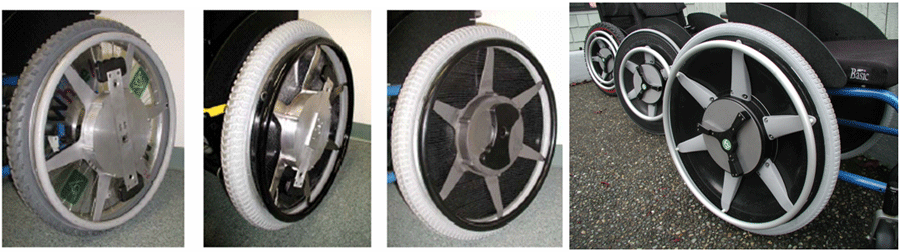 Figure 1. Photo of first through fourth generation of Magic Wheels.
Wheelchair users have long sought to transport themselves more efficiently to increase their mobility and independence. Currently the over 3 million manual wheelchair users in developed countries (over 1.8 million in U.S.) suffer limited mobility on inclines (hills, sloping and uneven sidewalks, curb cuts and driveways) as well as uneven terrain such as grass, gravel, sand, and thick carpeting. Only brute force allows manual wheelchair users to overcome these obstacles, at significant cost to their bodies -- 20% to 80% experience shoulder pain and 30% to 70% wrist pain. [1-7]
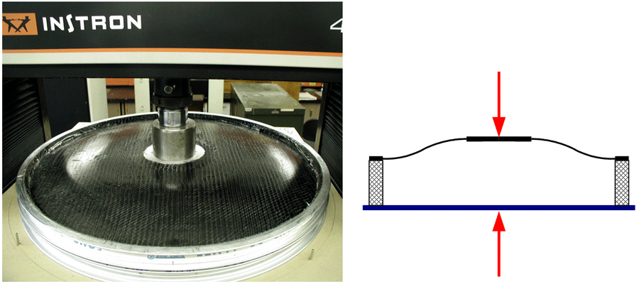 Figure 2: Axial Test
There have been many attempts to correct these limitations, but few have had mainstream success. Electric-powered wheelchairs are vastly too expensive for the average consumer, and other manual wheelchair designs have limitations on hill climbs, braking, and other problems. MagicWheels, Inc has developed a two-speed manual wheelchair that allows the user to freely access and navigate through areas that they could not previously.[8] A patented two-speed gear drive delivers an elegant solution that doesn’t depend on complex electronics, computers or cumbersome and expensive electric motors with heavy batteries. The second speed (2:1 gear ratio) helps reduce muscle stress and strain while doing hill climbs, and also assists in braking. A great asset of this new wheelchair design is that the new wheel fits and locks into a standard manual wheelchair using a quick-release mechanism that is compatible with industry standard axles and receiver bushing. [9]
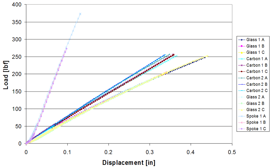 Figure 3. Graph of load vs. displacement graph data for axial loading test, third generation wheels
This new transmission had one major problem. The transmission for the Magic Wheels would increase the width of a standard wheelchair unless there are significant modifications made to the design. This problem was solved by developing a new type of wheel that is dish shaped and does not use spokes like standard wheelchair wheels. This new wheel is made of a foam core and fiber reinforced polymer composite skin to add additional strength to the wheel. [10] This approach allows the wheel to be lightweight, strong, and be shaped in a design that will allow for the transmission to be mounted properly. The wheel also incorporates a new bearing system only ½” thick to accommodate the thin composite wheel. The new dish shaped composite wheel is a critical component of Magic Wheels’ that allows the 2-speed transmission to be mounted deep inside the outboard wheel area and hence does not increase the width of the chair. In addition the composite wheel also provides a shiny smooth surface to prevent catching fingers between the push rim drive spokes and the outboard wheel surface
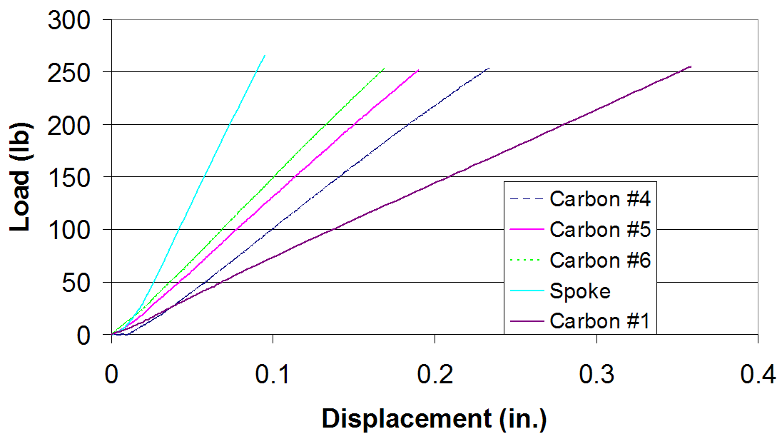 Figure 4. Graph of load vs. displacement data for axial loading test, fourth generation wheels
The pictures of prototype wheels below show the effect of the thin dish shaped composite wheel. In the left picture the 2-speed transmission is mounted on a spoke wheel and the hub & shifters protrudes outboard of the push rim. The 2nd picture shows an early version of the thin dish shaped composite wheel, the transmission is about 1 ¾” further inboard (note bent push rim drive spokes) and in the 3rd generation (3rd picture) the shift handle could be mounted on the surface of the drum without extending outboard of the push rim. In the far right picture, three versions of the 4th generation of Magic Wheels are shown.
METHODOLOGY
Two generations (3rd and 4th) of composite wheelchair wheels and one industry standard Quickieä spoke wheel were received for mechanical evaluation. The objective of the wheel testing was to compare the stiffness and strength of the composite wheels with a standard spoke wheel. The composite and spoke wheels were subject to 4 different loading conditions to measure:
- Axial strength and stiffness
- Bending (out of plane) strength and stiffness
- Radial strength and stiffness
- Torsional (in plane) strength and stiffness
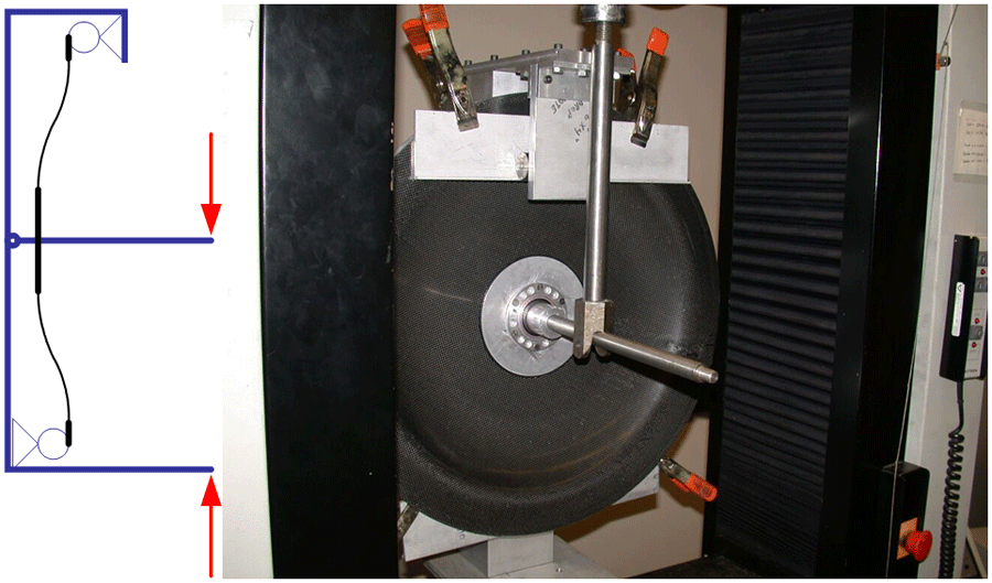 Figure 5: Bending test
Loads were applied using a computer controlled Instronä 4500 load frame at a loading rate of 0.1 inch/minute using specially designed fixtures for each test, custom built by the University of Washington for this purpose. Load and displacement data were acquired by computer. Wheels were loaded and unloaded a minimum of three times to at least twice the design load. The 3rd generation composite wheels were 2 carbon fiber composite wheels and 2 glass fiber composite wheels with a foam core mounted to a standard aluminum rim. Based on the axial and bending test results, the carbon fiber was selected for the 4th generation wheels were reinforced for additional axial and bending stiffness with a composite “doubler”; a ring shaped extra layer of composite around the hub.
RESULTS
More detailed descriptions and experimental results for each of the 4 loading conditions are presented below.
Axial Loading
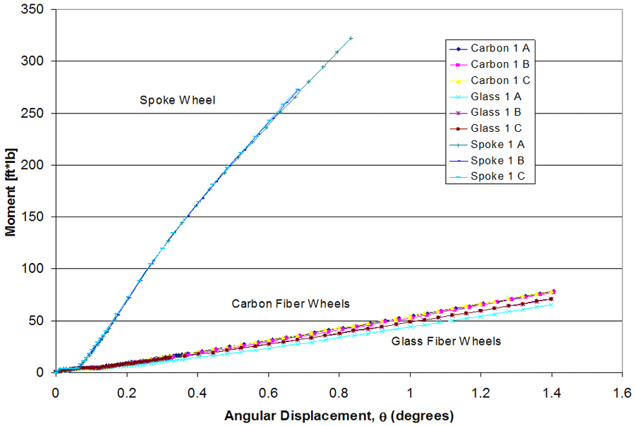 Figure 6. Graph of moment vs. angular deflection data for the third generation of composite wheels
The axial test was designed to test the wheels in the event that a load was placed against the midpoint of the wheel. Figure 2 describes this fixture, with the red arrows acting as the load and the specimen in the convex orientation. Representative load vs. displacement data are presented in figure 3. The load-displacement curves were all linear, except for some nonlinearity at the toe of curve which is expected. There was no significant change in the load–displacement data between the five load-unload cycles. This linear elastic behavior is indicative of loading without any damage. Visual inspection of the wheels under load and after removal of load did not reveal any damage to the wheels. The spoke wheel was considerably stiffer than either the carbon fiber or glass fiber composite wheels. The carbon fiber composite wheels were slightly stiffer than the glass fiber composite wheels. None of the wheels failed during testing.
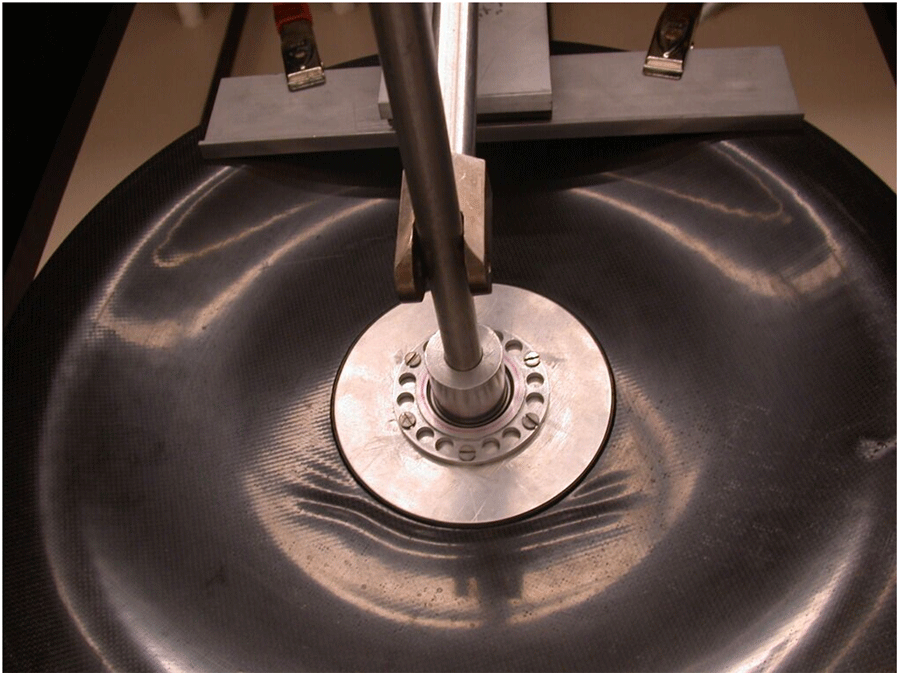 Figure 7. Photo of wrinkle noted in skin of third generation composite wheel under bending moment
The 4th generation of composite wheels from MagicWheels (#’s 4, 5 & 6) were three carbon fiber composite wheels with a thicker foam core and two wheels were selectively reinforced with an additional carbon fiber ply, coined “doublers”. The objectives of the 4th generation testing were to determine the effect of: 1) using a thicker foam core, 2) adding additional carbon fiber reinforcement and 3) two different types of adhesives. The load displacement data for these three wheels is given in figure 4. The thicker foam core increased the axial stiffness compared to the first generation carbon fiber wheels. The additional carbon fiber doublers also increased the stiffness. There was a slight difference in the stiffness with the different adhesives. The wheel bonded with the film adhesive was slightly less stiff than the wheel bonded with paste adhesive. The stiffness of the best 4th generation wheel was approximately twice that of the 3rd generation carbon wheel, however, it was still less stiff than a spoke wheel. None of the 4th generation wheels had any discernable damage after testing. Table I summarizes the 4th generation testing.
| Wheel Type | Description | Stiffness (lb/in) |
|---|---|---|
| Spoke | Original Spoked Wheel | 2927.6 |
| Carbon #1 | Old Composite Wheel | 716.87 |
| Carbon #4 | Prepreg Adhesive w/o Doubler | 1157.1 |
| Carbon #5 | Prepreg Adhesive w/ Doubler | 1365.9 |
| Carbon #6 | 2 Part Epoxy w/ Doubler | 1533.5 |
Bend Loading:
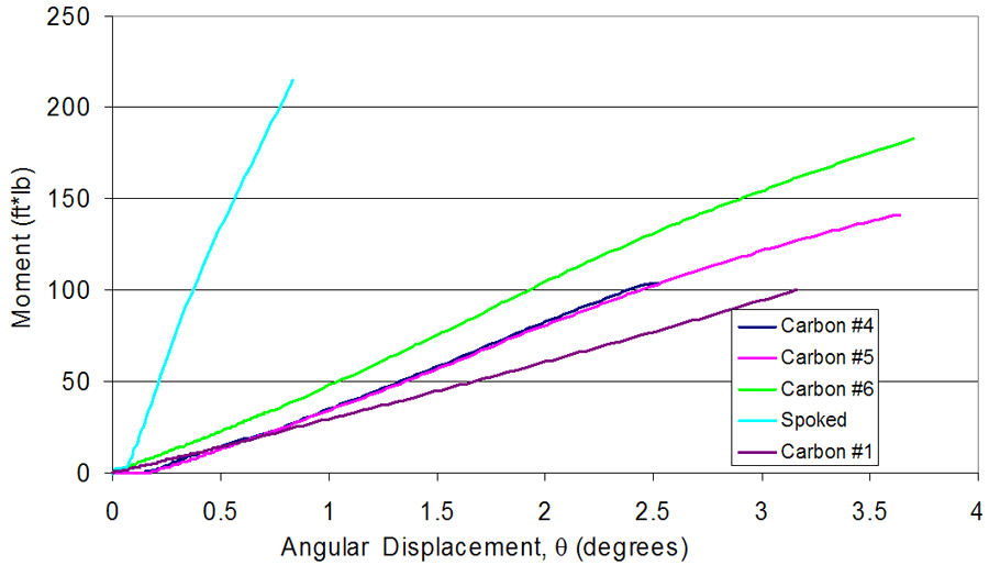 Figure 8. Graph of moment vs. angular deflection data for the fourth generation of composite wheels
The bend test was designed to simulate out of plane loading that may occur while transversing across an incline or tipping up on one wheel. The basic principle of this test was to create a moment on the wheel using a lever and a load placed at the end of the lever. This moment applied a force on the wheel at the hub, which causes the wheel to bend. The rim of the wheel was supported with rollers to allow movement in the direction of loading to prevent radial loading of the wheel as shown in figure 5. A minimum of 150lbs force was applied to all wheels which produced minimum bending moments of 100 ft-lbs. Representative moment vs. angular deflection data upon loading are presented in Figure 6. The moment-angular displacement curves were all linear, except for some nonlinearity at the toe of curve which is expected. There was no significant change in the load–displacement data between the three load-unload cycles. Visual inspection of the wheels under load revealed a slight wrinkle on the top and bottom of the aluminum disc near the hub as shown in figure 7. After removal of load no damage was evident in any of the wheels. The spoke wheel was considerably stiffer than either the carbon fiber or glass fiber composite wheels. The carbon fiber composite wheels were slightly stiffer than the glass fiber composite wheels. None of the wheels failed during testing.
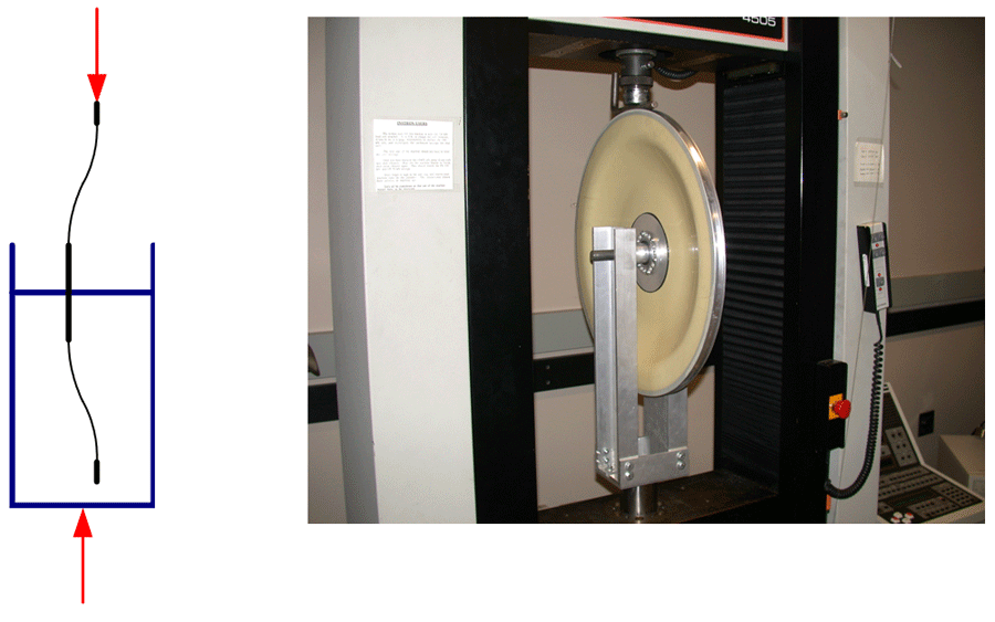 Figure 9. Schematic drawing and photo of the radial loading test
The moment vs. angular deflection data for the 4th generation of composite wheels from magic wheels is given in figure 8. The thicker foam core increased the axial stiffness compared to the first generation carbon fiber wheels by increase the moment of inertia. The additional carbon fiber doublers also increased the stiffness. There was a slight difference in the stiffness with the different adhesives. The wheels bonded with the film adhesive was slightly less stiff than the wheel bonded with paste adhesive. The stiffness of the best 4th generation wheel was approximately twice that of the 3rd generation carbon wheel, however it was still less stiff than a spoke wheel. None of the 4th generation wheels had any discernable damage after testing. Table II summarizes the 4th generation testing.
| Wheel Type | Description | Stiffness (lb*ft/degree) |
|---|---|---|
| Spoke | Spoke wheel | 34.68 |
| Carbon #1 | Old Composite Wheel | 3.91 |
| Carbon #4 | Prepreg Adhesive w/o Doubler | 5.44 |
| Carbon #5 | Prepreg Adhesive w/ Doubler | 5.29 |
| Carbon #6 | 2 Part Epoxy w/ Doubler | 6.46 |
Radial Loading
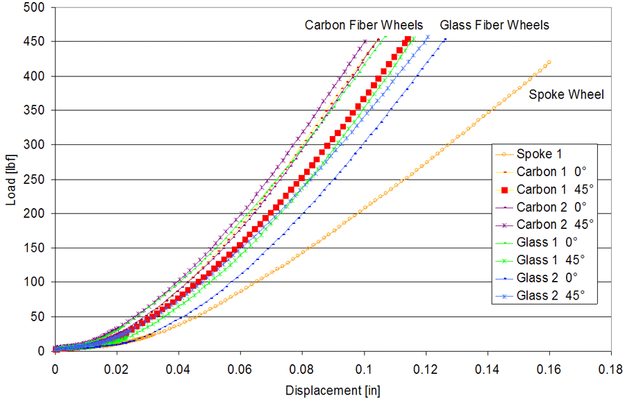 Figure 10. Graph of load vs. displacement graph data for radial loading test
The radial test was designed to load the wheel without a tire to test the stiffness and strength of the hub and rim. The hub of the wheel was supported by axel through a fixture similar to a bicycle fork and a load was applied to the rim of the wheel as shown in figure 9. A minimum of 400 pounds of force was applied to all wheels, well past the design load. The composite wheels were tested at 0 and 45 degrees with respect to the fiber direction. Representative load vs. displacement data upon loading are presented in figure 10. The load-displacement curves were relatively linear, except for some nonlinearity at the toe of curve which is expected. There was no significant change in the load–displacement data between the five load-unload cycles. This linear elastic behavior is indicative of loading with out any damage. Visual inspection of the wheels under load and after removal of load did not reveal any damage to the wheels. The composite wheels are significantly stiffer than the spoke wheel. The carbon fiber composite wheels were slightly stiffer than the glass fiber composite wheels. None of the wheels failed during testing.
Torsion Loading
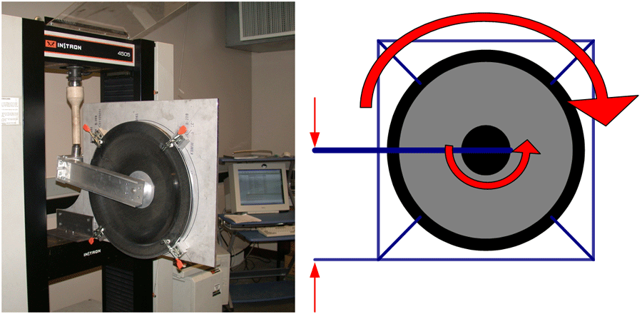 Figure 11. Schematic drawing and photo of the torsional (in-plane) loading test (Click image for larger view)
 The torsion test used the same fork fixture as the radial test, but it was rotated 90 degrees and fixed to the hub where the transmission is fastened. The outer rim of the wheel was clamped to prevent rotation and a load was applied to the fork to simulate the torque that would be applied to the wheel hub through the transmission as shown in figure 11. A minimum of 200 ft-lbs of torque was applied to all composite wheels; the spoke wheel was not tested since it was not designed for torque loading. Representative torque vs. angular displacement data upon loading are presented in Figure 12. The load-displacement curves were relatively linear, except for some nonlinearity at the toe of curve which is expected. There was no significant change in the load–displacement data between the five load-unload cycles. This linear elastic behavior is indicative of loading without any damage. Visual inspection of the wheels under load and after removal of load did not reveal any damage to the wheels. The carbon fiber composite wheels were slightly stiffer than the glass fiber composite wheels. None of the wheels failed during testing. The torsional loads during testing were much higher than expected to be applied by users [11-13].
 Figure 12. Graph of torque vs. angular displacement for torsion loading test (Click image for larger view)
 SUMMARY
- Axial loading: The reinforced carbon fiber wheels are not as stiff as a spoke wheel, but are sufficient to meet requirements. Strength exceeded design strength.
- Out of plane loading (bending): The reinforced carbon fiber wheels are not as stiff as a spoke wheel, but are sufficient to meet requirements. Strength exceed design strength by
- Radial Loading of Magic Wheels Composite Wheels: The carbon fiber and glass fiber composite wheels are significantly stiffer than the spoke wheel and exceed the requirements.
- Torsional Loading: The carbon fiber and glass fiber composite wheels were able to sustain high torsional loading, greater than design. Hand driven spoke wheels are not designed for this type of loading and were not tested.
REFERENCES
- Curtis, K.J. and Black, K.(1999). Shoulder pain in Female Wheelchair Basketball players, JOSPT; 29(4): 225-31.
- Curtis, K.A., Drysdale, G.A., Lanza R.D., Kolber M., Vitolo R.S., West R., (1999). Shoulder pain in wheelchair users with tetrapeligia and papalegia, Arch Phyd. Med Rehabil Apr,80(4) 453-7.
- Curtis K. A., and Dillion, D.A. (1985). Survey of wheelchair athletic injuries: common patterns and prevention, Paraplegia, jun 23(3);170-5.
- Finley, MA, Rasch, E.K., Keyser, R.E., Rodger, M.M.(2004). The biomechanics of wheelchair propulsion in individuals with and without upper limb impairment, J Rehabil Res Dev. 41(3b): 395-402.
- Finley, M.A., Rodger, M.M.(2004). The biomechanics of wheelchair propulsion in individuals with and exclusive of upper limb impairment, J Rehabil Res Dev. 41(3b): 385-395.
- Stanley, R.K., Stafford D.J., Rasch, E., Rodgers, M.M. (2003). Development of a functional assessment measure for manual wheelchair users, J Rehabil Res Dev. Jul-aug; 40(4): 301-307.
- Finley, M.A., Gordes K.L., Meginniss, S, Rodgers, M.M. (2006). Effect of two-speed manual wheelchair wheel on shoulder pain in wheelchair users, 22nd International Seating Symposium, Vancouver, B.C. - March 1-4, 2006.
- www.magicwheels.com
- Meginniss, Stephen. (2004). Two-Speed Wheel Assembly for Manual Wheelchairs, with a quick release mounting capability, US Patent and Trademark Office, Patent # 6,805,371 Oct.19, 2004
- Argarwal, B.D. and Broutman, L.J. (1990) Analysis and Performance of Fiber Composites, 2nd Ed. John Wiley & Sons, Inc. New York.
- An, K. N., Guo, L.Y., Su, F., Zhao, K.D. (2003). Moment Generation in Wheelchair Propulsion, Engineering in Medicine, Vol. 217. Pg 405-413.
- Boninger M.L., Cooper R.A., Robertson R.N., Shimada S.D. (1997). Three-dimensional pushrim forces during two speeds of wheelchair propulsion, Am J Phys Med Rehabil. Sep-Oct;76(5) 420-6.
- Robertson, R.N., Boninger, M.L., Cooper, R.A. Shimada, S.D. (1996). Pushrim forces and joint kinetics during wheelchair propulsion, Arch Phys Med Rehabil. sep;77(9) 856-64.
Author Information:
Brian D. Flinn
Department of Materials Science and Engineering
302 Roberts Hall, Box 352120
University of Washington
Seattle, WA 98195
(206) 616-906
Highlights
- Source Ordered
- No Tables
- Very Compatible
Gargoyles
Disney produced a television show in the mid 1990s called Gargoyles. It's a great show and I'm a big fan. A few years ago Disney started to release the show on DVD. The last release was of season 2, volume 1. That was two years ago. Volume 2 has not been released. Why? Poor sales. So if you should find yourself wanting to support my work, instead I ask you pick up a copy of season 2, volume 1. It's a great show and you might find yourself enjoying it.