Evaluation of Titanuim Wheelchairs Using the ANSI/RESNA Standards
Hsin-yi Liu, BS, Rory A. Cooper, PhD, Shirley G. Fitzgerald, PhD, Jonathan L. Pearlman, MSc, Samuel Connor, BS, Ana Souza, B.S
Department of Rehabilitation Science and Technology, University of Pittsburgh
Human Engineering Research Laboratories, VA Pittsburgh Healthcare System, Pittsburgh PA
Abstract:
We performed wheelchair standard tests on twelve commercial manual titanium wheelchairs to determine their durability and stability, although testing is still in progress. Thus far two wheelchairs have failed in double-drum testing due to fracture at the heated effected zone of a weld and due to metal fatigue. The results of static stability at present show some unique characteristics from lightweight and ultralight weight wheelchairs that may need more attention during testing procedures.
Keywords:
wheelchair tests, manual wheelchair
Introduction:
How to choose a proper and suitable wheelchair is quite complicated. The ANSI/RESNA standard tests serve as a source of information about quality and to permit comparison of results. The content of standard tests covers many aspects of wheelchairs that would affect usage and selection, such as dimensions, statistic stability, brake effectiveness, strength, and durability.
According to Smith et.al. [1], general expectations among wheelchair users are improving their quality of life, and maintaining or achieving a certain level of mobility. Users expect that their wheelchairs are comfortable, easy to propel, safe, and good-looking. Comfortable propulsion and support are very important. Developing a lighter and more functional wheelchair is a goal for the design of manual wheelchairs. The titanium wheelchair is a product in response to this goal. The ANSI/RESNA standards are developed to set and reveal the minimum quality of wheelchairs. In previous reports using ANSI/RESNA standards to evaluate ultralight weight wheelchairs, all made from aluminum, and lightweight wheelchairs, all made from steel, ultralight weight wheelchairs performed better than lightweight wheelchairs in the fatigue tests [2, 3]. The ultralight weight wheelchairs lasted more than five times as long as lightweight wheelchairs[2], but most of the ultralight weight wheelchairs experienced multiple component failures, such as bolts losing or caster stems broken. Although the integrity of the frame structure was not influenced by the component failures, multiple component failures would be annoying and may leave the user in a hazardous situation. Titanium is stronger than aluminum, so a titanium wheelchair could be made from less material than an aluminum wheelchair with the same strength of the frame, making the wheelchair lighter. The titanium wheelchairs tested were all ultralight models. The result of fatigue tests of titanium wheelchairs is important not only to understand durability, but also the type and frequency of the failures may influence the user’s quality of live and the satisfaction with the wheelchair[4].
Research Question:
- How does the durability of titanium wheelchairs compare to other wheelchairs previously tested?
- With what frequently and severity do the titanium wheelchairs fail during the fatigue tests?
- What is the static stability of titanium wheelchairs?
Methods:
Twelve titanium manual wheelchairs of 4 different models from 3 manufacturers were tested in this study, including TiLite ZRA (TiLite), Quickie Ti Titanium (Sunrise Medical), A4 Titanium and Top End Terminator Titanium (Invacare). We performed the tests following the methods prescribed by the ANSI/RESNA Wheelchair Standards. The test sections included overall dimensions and turning space (§5), seating and wheel dimensions (§7), static stability (§1), static, impact and fatigue strength (§8), and information disclosure, and documentation and labeling (§15). The failures during the fatigue tests were classified into three levels[5]. Class I failures represent minor adjustments or repairs that may be accomplished by the wheelchair user or an untrained person, such as tightening a loose bolt or screw. Class II failure include minor repairs that can be done by a repair technician or a bicycle mechanic, such as replacing flat tires and making complex adjustment of camber and wheel alignment. Class III failures describe structural damage that would immobilize the wheelchair, such as wheelchair frame breaking. The fatigue tests would come to an end when Class III failure occurred. If the wheelchair was still usable after achieving the required cycles in the standards, the wheelchair would go back to the fatigue tests until a permanent failure occurred to reveal its life cycles. For the purpose to comparing the fatigue life, the following formula was used to compute the equivalent number of cycles:
Total Cycles = ( Double-Drum Tester Cycles) + 30´( Curb-Drop Tester Cycles) (1)
All the data were reported with descriptive statistics (means and standard deviations). Analysis of variance (ANOVA) was used to test the differences of the total cycles and the result of the static stability among 4 models with levels of significance of p < .05. The durability of titanium wheelchairs was compared with other manual wheelchair types (depot, lightweight, and ultralightweight) by using survival curves.
Results:
The testing is still in proceeding. All the wheelchairs weighted 9 to 12 kg, and the overall dimensions were shown in Table 1. Two wheelchairs, Inva-04 and Inva-06 completed the testing, and both failed in the double drum test. Inva-04 (Top End Terminator) failed because the backrest canes broke at 86,950 cycles (figure 1a). A broken caster stem made Inva-06 (A4 Titanium) fail at 181,579 cycles (figure 2a). When Inva-04 was on the double-drum test, minor failures occurred three times because the right axel bolt kept coming out. The first stop was at 11,047 cycles for adjustment, and then at 24,069 and 56,039 cycles for the same problem in sequence. Some of the results of static stability test are shown in Table 2. Most of the wheelchairs have “negative angles” in the results for the least stable configuration in the rearward direction because the wheelchairs would tip backward immediately with the testing dummy on a level floor. The angle represents how steep the downhill slope was to make the casters stay on the platform.
| Wheelchair | Length | Width | Height | Mass |
|---|---|---|---|---|
| TiLite-01 | 790mm | 580mm | 810mm | 20lb/9.07kg |
| TiLite-02 | 820mm | 590mm | 810mm | 20lb/9.07kg |
| TiLite-10 | 810mm | 590mm | 765mm | 20lb/9.07kg |
| Inva-03 | 780mm | 620mm | 725mm | 20lb/9.07kg |
| Inva-04 | 800mm | 640mm | 720mm | 20lb/9.07kg |
| Inva-05 | 810mm | 635mm | 710mm | 20lb/9.07kg |
| Inva-06-A4 | 830mm | 650mm | 720mm | 25lb/11.33kg |
| Inva-11-A4 | 820mm | 650mm | 725mm | 25lb/11.33kg |
| Inva-12-A4 | 830mm | 630mm | 730mm | 25lb/11.33kg |
| Quik-07 | 820mm | 610mm | 795mm | 20lb/9.07kg |
| Quik-08 | 820mm | 580mm | 770mm | 20lb/9.07kg |
| Quik-09 | 820mm | 620mm | 775mm | 20lb/9.07kg |
| Forward | Rearward | Sideway | ||||||
|---|---|---|---|---|---|---|---|---|
| Front casters unlocked | Rear wheels locked | Rear wheels unlocked | ||||||
| Model | Least stable | Most Stable | Least stable | Most Stable | Least stable | Most Stable | Least stable | Most Stable |
| TiLite-01 | 21.7 | 29.5 | -16.8 | 11 | -14.6 | 20 | na | 21 |
| TiLite-02 | ||||||||
| TiLite-10 | 21.1 | -40 | 8.6 | -20.8 | 14.7 | na | 19.55 | |
| Inva-03 | 26.1 | 28.4 | 0 | 11.2 | -1 | 20.8 | na | 21.15 |
| Inva-04 | 25 | 25.4 | 2.5 | 10.8 | 9.4 | 19.1 | na | 20.8 |
| Inva-05 | 26 | 26.9 | -23.9 | 10.8 | -3.5 | 21.7 | na | 21.6 |
| Inva-06-A4 | 24.5 | 31 | -26.2 | 7.3 | -1.4 | 15.5 | 22.05 | 25.5 |
| Inva-11-A4 | ||||||||
| Inva-12-A4 | ||||||||
| Quik-07 | 19 | 34 | -22.4 | 16 | -4.5 | 29 | 19.75 | 23.75 |
| Quik-08 | 21.1 | 34.5 | -41.1 | 15.6 | -17.1 | 27.5 | 22.95 | 25.35 |
| Quik-09 | ||||||||
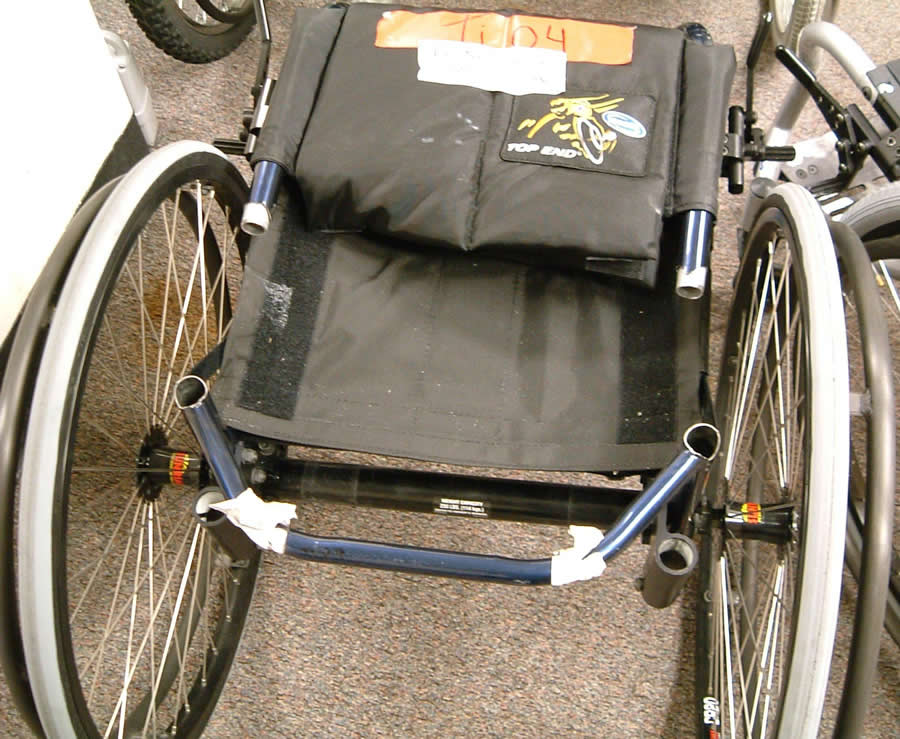
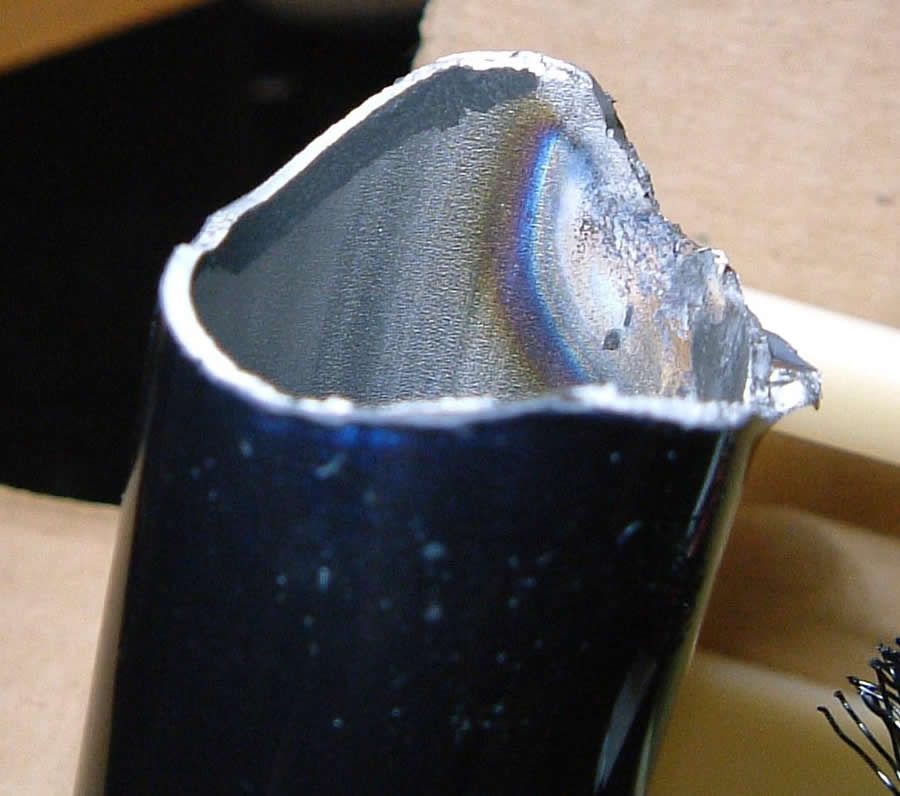
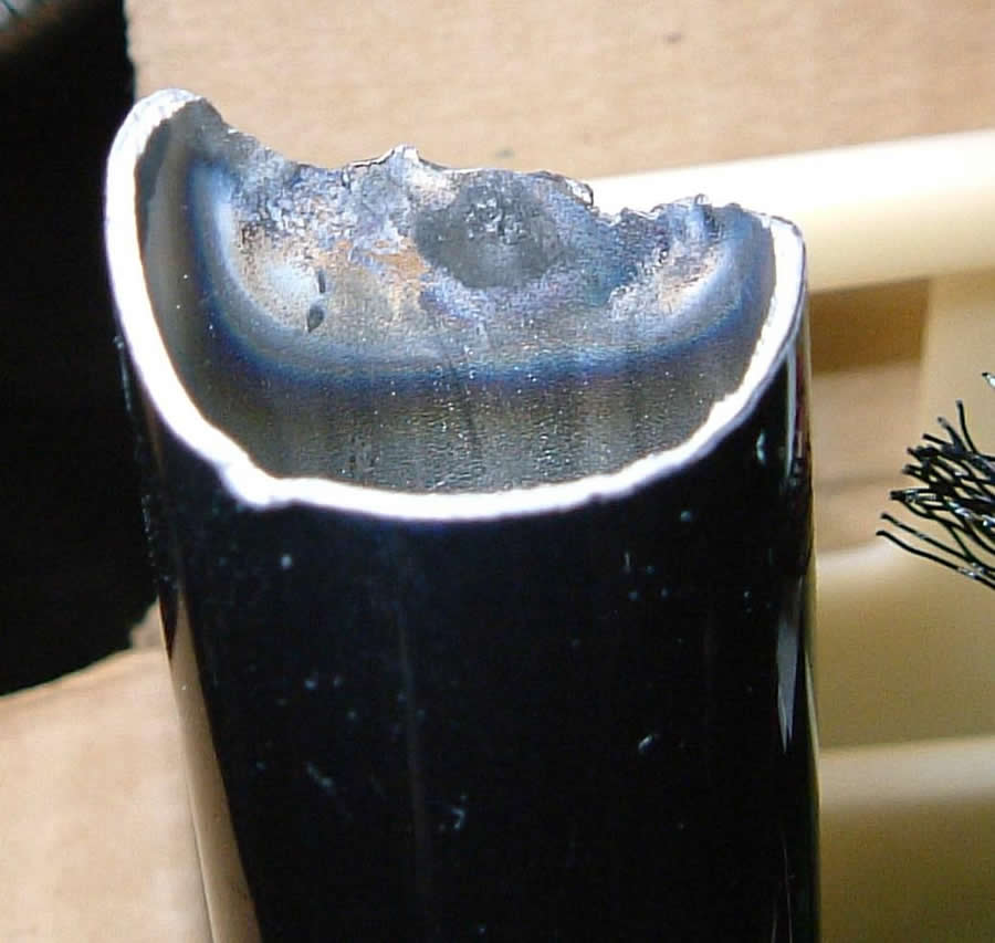
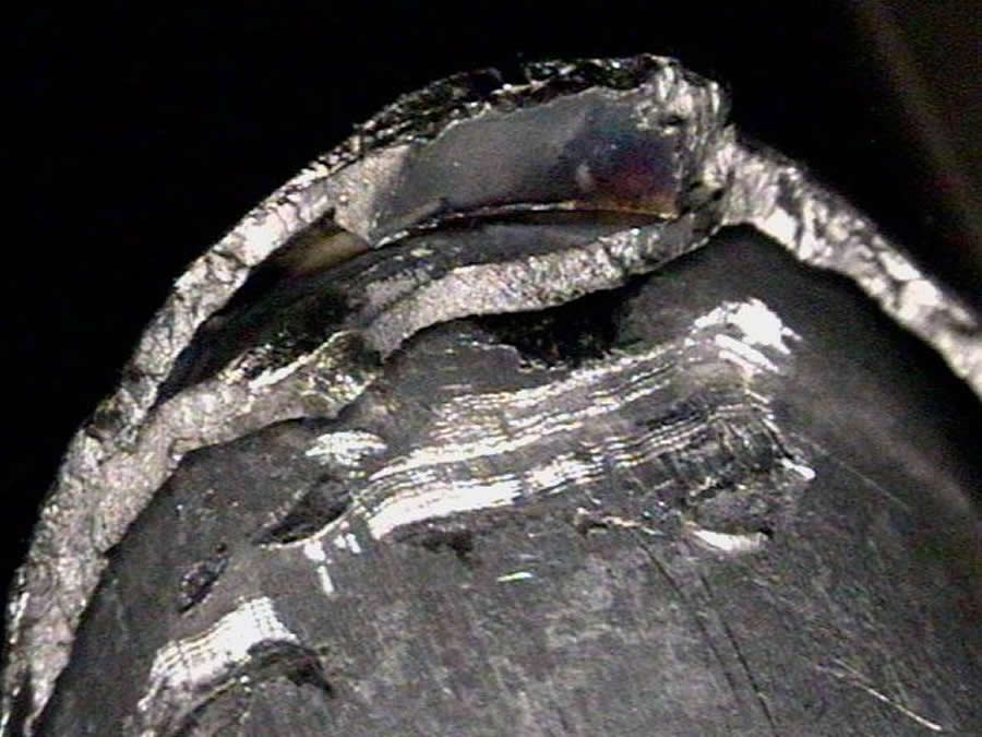 Figure: 1 The backcanes of Inva-04 are snapped in the double-drum test. (Click for larger view)
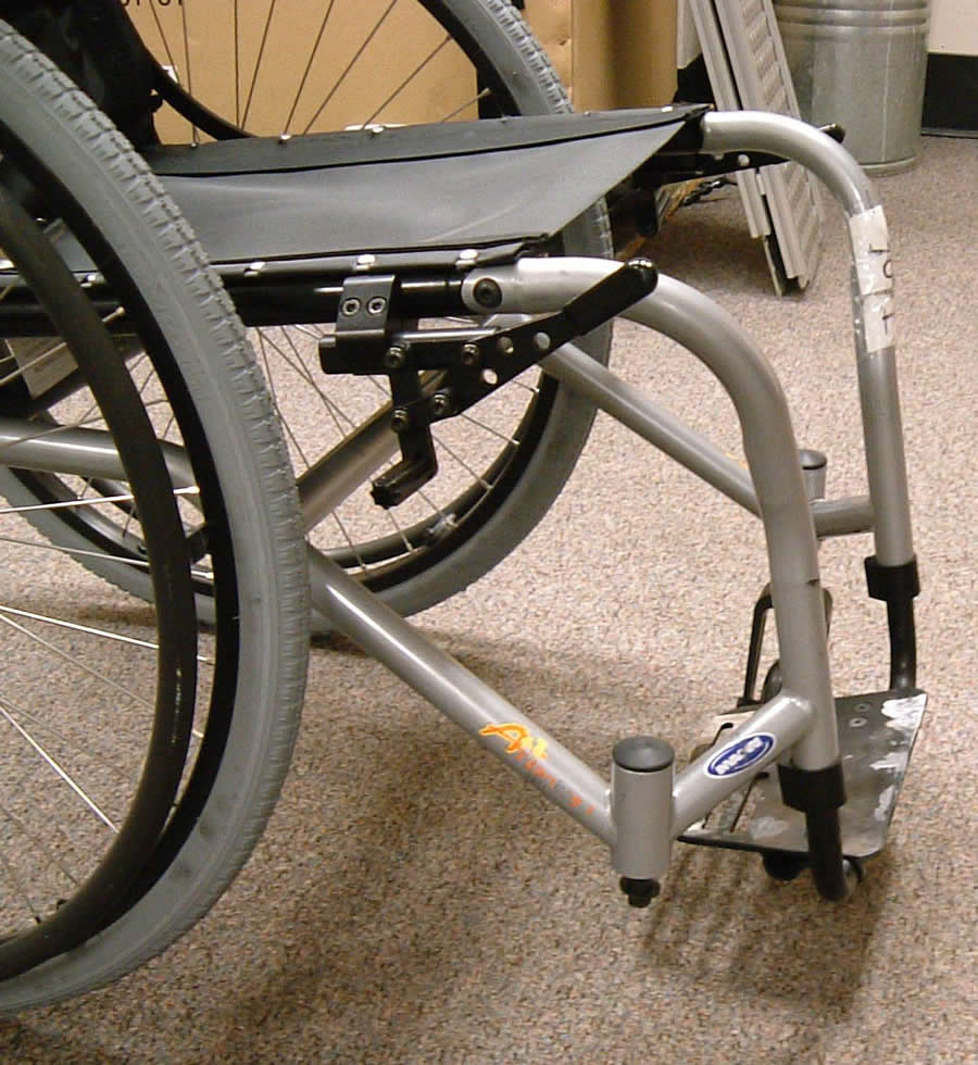
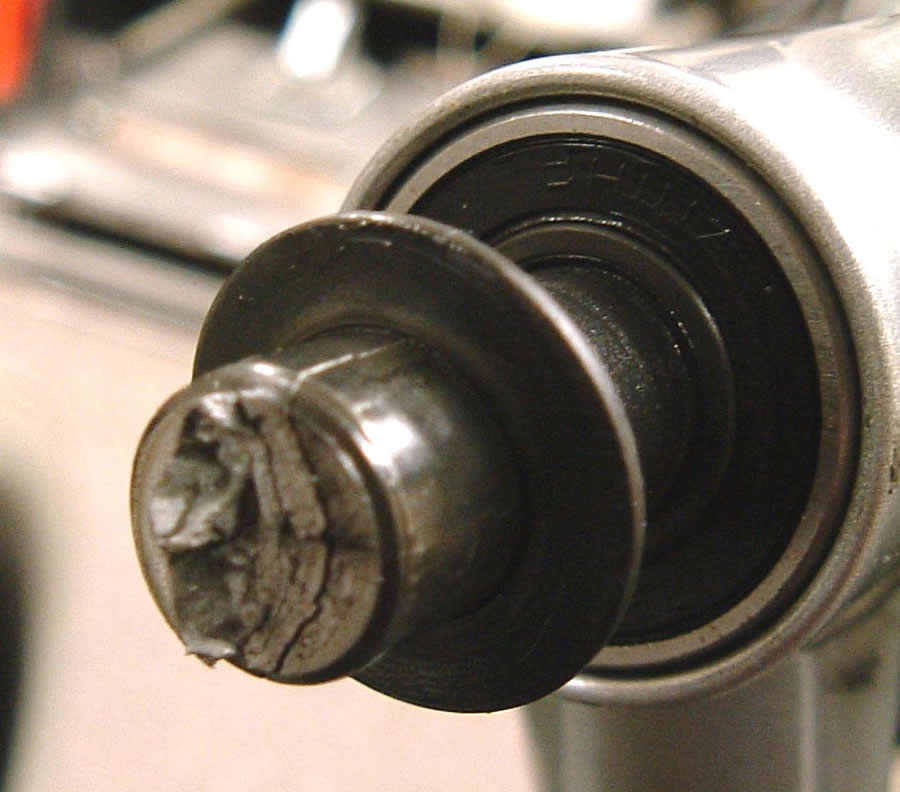
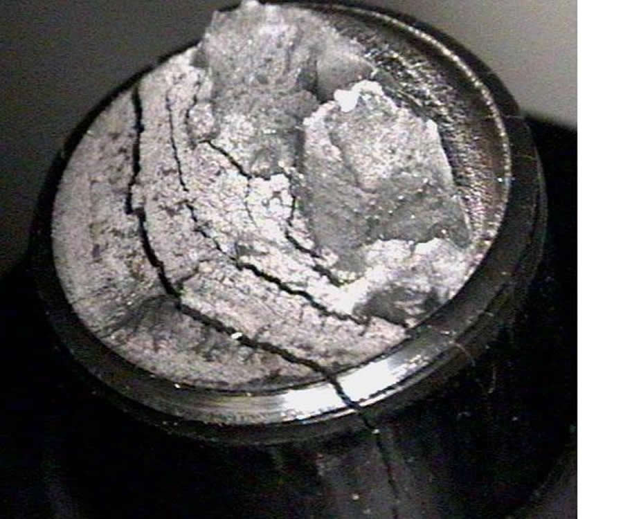
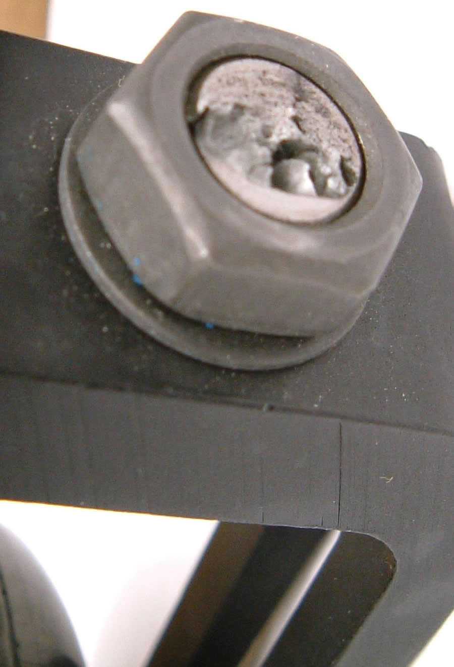
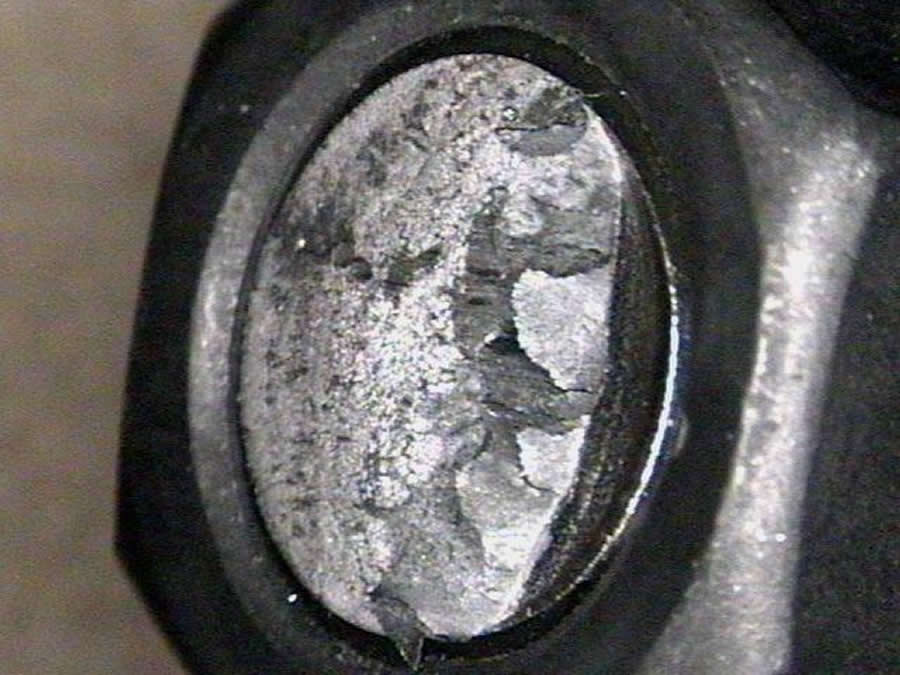 Figure 2: The caster stem of Inva-06 fractured in the double-drum test (Click for larger view)
Discussion:
Comparing with the results from the previous studies, the overall dimensions of Titanium wheelchairs in our study are smaller than other ultralight weight wheelchairs. The angle of knee flexion when the user sits on the Titanium wheelchair would be more than 90 degree. The Titanium wheelchairs are for everyday use, so the influence of their compact dimension on human body needs more thoroughly discussion in the future. The group of pictures in Figure 1 and Figure 2 show the broken surfaces and nearby areas taken with a regular digital camera and a microscope. At temperatures higher above 500°C, titanium has very high affinity for oxygen, nitrogen, and hydrogen[6]. Weld metal contamination by gas absorption can make titanium brittle, so the welding process must be protected from oxidation by an inert gas shield (argon or helium). When oxidation occurs, the oxide on the interacting surface would generate an interference color. In figure 1b and 1c, white, light blue and gray colors are on the heat affected zone, and it represents that titanium had high level of oxygen contamination during welding process. The fracture surface in 1d is quite shiny that also implies embrittlement may have caused the fracture of the backrest cane. In figure 2band 2c, the arrows highlight beach marks, the characteristic of fatigue fracture[7], and also represent the direction of fracture. The durability of the titanium wheelchairs would be revealed after the remainder of the wheelchairs complete the standard tests. Most of the titanium wheelchairs in this study have high adjustability, especially the axel position in horizontal direction. There is no limitation on the wheelchair objectively or in the manual, so the least stable configuration in rearward direction we could achieve would make the wheelchair tilt backward, which can be dangerous for the researchers or engineers performing the static stability tests. Manufacturers should consider limiting adjustability to prevent this potentially hazardous condition. For the model of TiLite ZRA in the least stable configuration in forward stability test, the least angle resulted by adjusting the rear wheel axels to the midpoint of the total length it could travel. According to the manual of standard tests, the least stable configuration in forward direction is achieved by moving the rear wheels and seat into a forward position to shift the center of mass to the anterior part of the base of support. For all the wheelchairs in this study, when we adjusted the rear wheel forward, the seat position was move backward relatively, and made the center of mass shift backward. The method of static stability test of least stable in forward direction needed to be modified to achieve the correct results.
Acknowledgement:
The authors thank for the help and generosity from all faculties, staffs, and colleagues in the Human Engineering Research Laboratories. This research was supported by VA-RR&D grand # B3142C.
Reference:
- Smith, C., M. McCreadie, and J. Unsworth, Prescribing wheelchairs: the opinions of wheelchair users and their carers. Clinical Rehabilitation, 1995. 9(1): p. 74-80.
- Cooper, R.A., et al., Evaluation of selected ultralight manual wheelchairs using ANSI/RESNA standards. Archives of Physical Medicine & Rehabilitation, 1999. 80(4): p. 462-7.
- Cooper, R.A., et al., Performance of selected lightweight wheelchairs on ANSI/RESNA tests. American National Standards Institute-Rehabilitation Engineering and Assistive Technology Society of North America. Archives of Physical Medicine & Rehabilitation, 1997. 78(10): p. 1138-44.
- Shirley G. Fitzgerald, P.D.M.C., PhD, OTR/L; Rory A. Cooper, PhD, Issues in maintenance and repairs of wheelchairs: A pilot study. Journal of Rehabilitation Research & Development, 2005. 42: p. 853-862.
- Cooper, R.A., Wheelchair selection and configuration 1998, New York Demos.
- Technology, W.C.f.M.J. Weldability of materials. Titanium and titanium alloys [cited; Available from: http://www.twi.co.uk/j32k/protected/band_3/jk24.html.
- Ali Faterini, R.I.S., Henry Otten Fuchs, Macro/Micro Aspects of Fatigue of Metals, in Metal Fatigue in Engineering 2001, Wiley-IEEE. p. 33-41.
Highlights
- Source Ordered
- No Tables
- Very Compatible
Gargoyles
Disney produced a television show in the mid 1990s called Gargoyles. It's a great show and I'm a big fan. A few years ago Disney started to release the show on DVD. The last release was of season 2, volume 1. That was two years ago. Volume 2 has not been released. Why? Poor sales. So if you should find yourself wanting to support my work, instead I ask you pick up a copy of season 2, volume 1. It's a great show and you might find yourself enjoying it.